Display system based on zoom microlens array

A microlens array and display system technology, applied in the field of 3D display, can solve the problems of poor portability and practicability, easy to cause visual fatigue, etc., and achieve good 3D effect

Inactive Publication Date: 2020-01-31
SUZHOU UNIV
View PDF7 Cites 3 Cited by
  • Summary
  • Abstract
  • Description
  • Claims
  • Application Information

AI Technical Summary

Problems solved by technology

[0004] The purpose of the present invention is to provide a display system based on a zoom microlens array to solve the problems in the prior art that glasses are needed, portability and practicability are poor, visual fatigue is easy to occur, and nausea and dizziness will occur after long-term observation

Method used


Image

  • Display system based on zoom microlens array
  • Display system based on zoom microlens array
  • Display system based on zoom microlens array

Examples


Embodiment 1

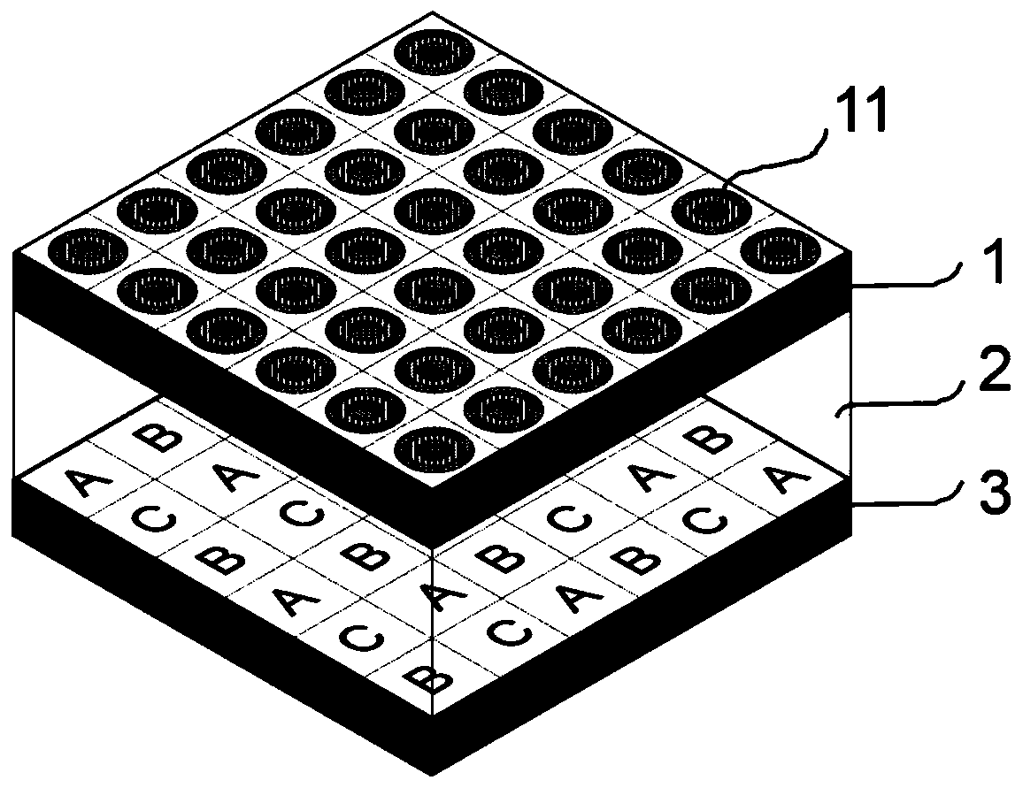
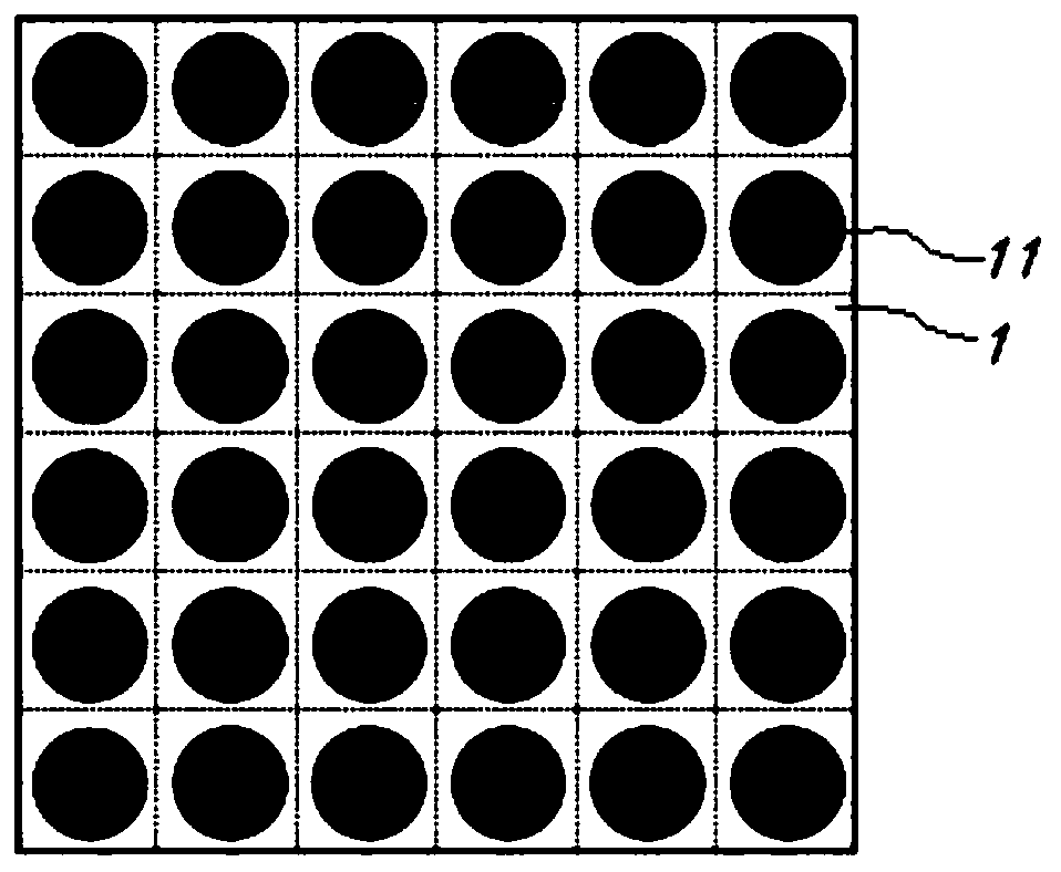
[0053] ginseng figure 1 with figure 2 As shown, in this embodiment, the microlens layer 1 is a microlens array composed of 6*6 microlens units 11, such as Figure 4 As shown, the micro-texture layer 3 is a micro-character arrangement composed of letters A, B, and C, and each micro-lens unit 11 in the micro-lens layer 1 corresponds to each letter in the micro-texture layer 3, and different letters The focal lengths of the corresponding microlens units 11 are different, and the focal lengths of the microlens units 11 corresponding to the same letter are the same, that is, the focal lengths 11 of the microlens units corresponding to the letter A are all the same, and the focal lengths of the microlens units 11 corresponding to the letter B are all the same. The focal lengths 11 of microlens units corresponding to C are all the same, but these three focal lengths are different.

[0054] Therefore, through the zoom microlens array can be observed as Figure 5 In the layered dis...

Embodiment 2

[0057] ginseng Image 6 As shown, in this embodiment, the microlens layer 1 is a microlens array composed of 5*5 microlens units 11, and the corresponding microtexture layer 3 is as follows Figure 7 As shown in the micro-character arrangement composed of letters A-Y, each letter in the micro-texture layer 3 corresponds to the micro-lens unit 11 in the micro-lens layer 1 one by one.

[0058] The microlens units 11 corresponding to different letters in the microlens layer 1 have different focal lengths, that is, each of the 25 microlens units 11 has a different focal length. Therefore, through the microlens layer 1, it can be observed that the letters A-Z are divided into 25 layers. Display, each layer displays different letters to achieve a 3D effect.

[0059] The micro-graphic layer 3 and the micro-lens layer 1 are arranged to meet the conditions of Moiré magnification, and the structure can realize the effect of hundreds of times magnification, and can realize "floating", "...

Embodiment 3

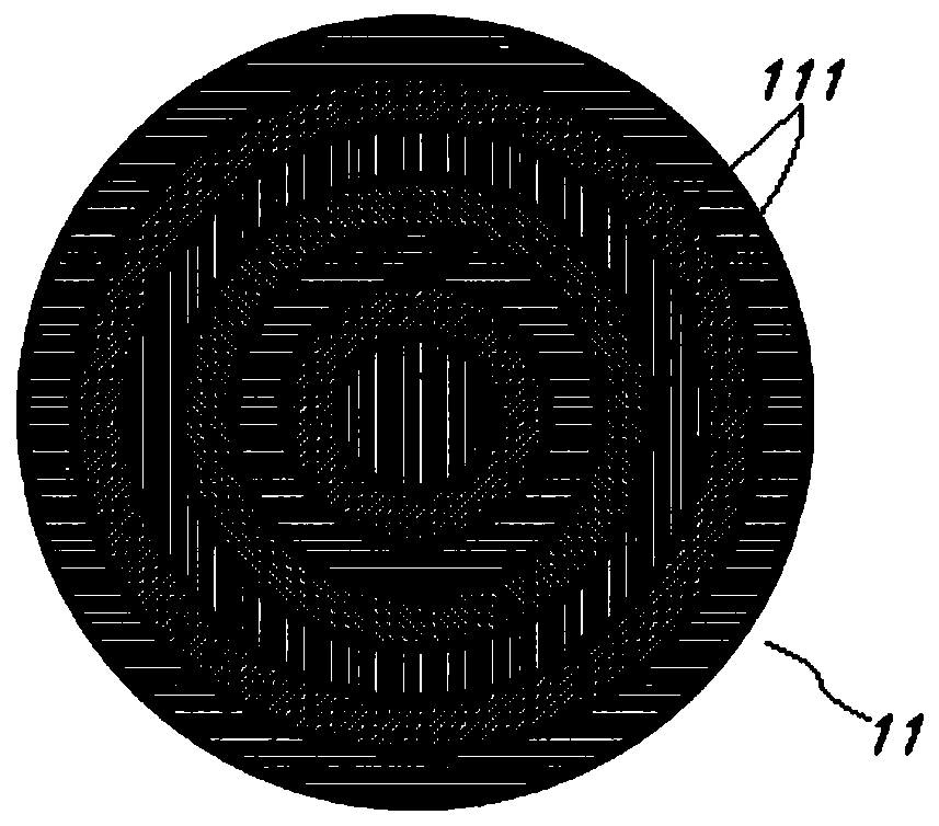
[0061] Figure 8 A schematic diagram of realizing 3D display for this embodiment, such as Figure 9 As shown, the micro-texture layer 3 is a circular pattern, and the micro-lens layer 1 is composed of a large number of micro-lens units 11 with different focal lengths.

[0062] The focal length of each microlens unit 11 in the microlens layer 1 is different, and each microlens unit 11 presents the images of each part of the circular pattern on different focal planes, and the circular pattern is divided into many layers for display. A 3D effect can be achieved, so that through the microlens layer 1 it is possible to observe Figure 10 The three-dimensional spherical structure shown.


PUM


Abstract

The invention discloses a display system based on a zoom microlens array. The display system comprises a microlens layer and a micro image-text layer, a dielectric layer is arranged between the microlens layer and the micro mage-text layer, the microlens layer is composed of a plurality of microlens units distributed in an array mode, different microlens units are the same or different in the focal length, and each microlens unit is of a pixelated space variable parameter micro-nano structure. The focal lengths of the microlenses in different areas are changed to realize layered display of micro images and texts, patterns have a good 3D effect, and a dynamic amplification pattern can be formed according to the Moire magnification principle.

Description

technical field [0001] The invention belongs to the technical field of 3D display, and in particular relates to a display system based on a zoom microlens array. Background technique [0002] 3D technology has experienced more than ten years of development and has achieved very fruitful results. The early solution to realize 3D display is to use special glasses to induce the binocular parallax of the observer by providing different images for each eye so that people can perceive 3D information. The biggest disadvantage of this type of technology is the viewing comfort, which is caused by the adjustment of eyeballs and the depth difference of visual perception. When viewing a stereoscopic display, the eyes must observe the screen to perceive a clear image. This kind of parallax makes the perception of the visual system and the brain different, and people will feel visual fatigue, which leads to discomfort during long-term observation, and it is easy to cause symptoms such as...

Claims


Application Information

Patent Timeline
Patent Type & Authority Applications(China)
IPC IPC(8): G02B30/27
Inventor 叶燕叶红宋志路畅王钦华陈林森
Owner SUZHOU UNIV
Why Eureka
Try Eureka