
Optimised tunnel ventilation device

A ventilation flow and fan technology, applied in mine/tunnel ventilation, pump devices, parts of pumping devices for elastic fluids, etc., can solve problems such as pressure loss, reduce power consumption, avoid flow separation, Create simple effects

Pending Publication Date: 2020-01-31
MOSEN
View PDF6 Cites 0 Cited by
  • Summary
  • Abstract
  • Description
  • Claims
  • Application Information

AI Technical Summary

Problems solved by technology

However, since the nozzle trailing edge of the tail is shaped oval, it is not feasible to attach a commercially available bell mouth on the nozzle trailing edge, which in turn implies a significant pressure loss through the jet fan
[0005] The applicant believes that there is still room to improve the energy efficiency of the longitudinal tunnel ventilation system

Method used


Image

  • Optimised tunnel ventilation device
  • Optimised tunnel ventilation device
  • Optimised tunnel ventilation device

Examples


Embodiment Construction

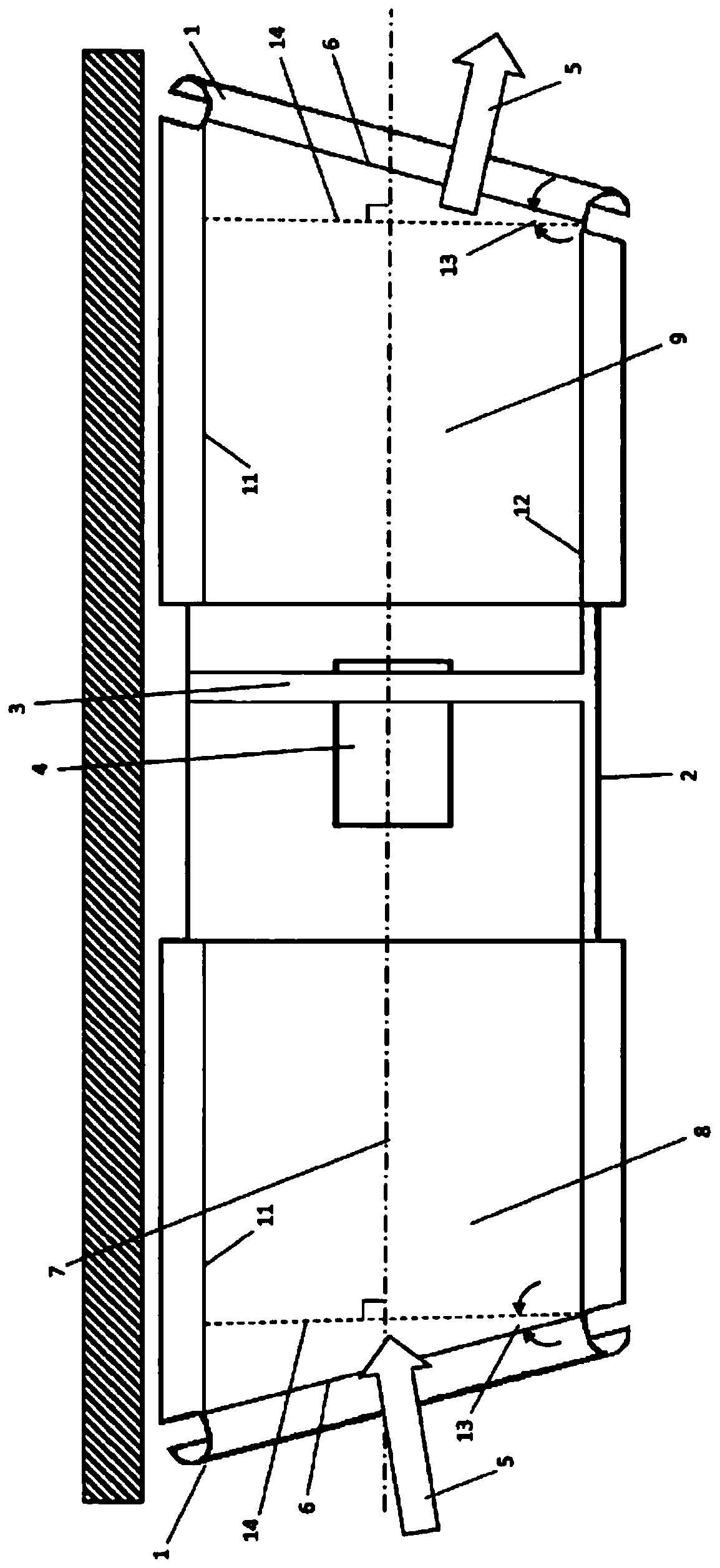
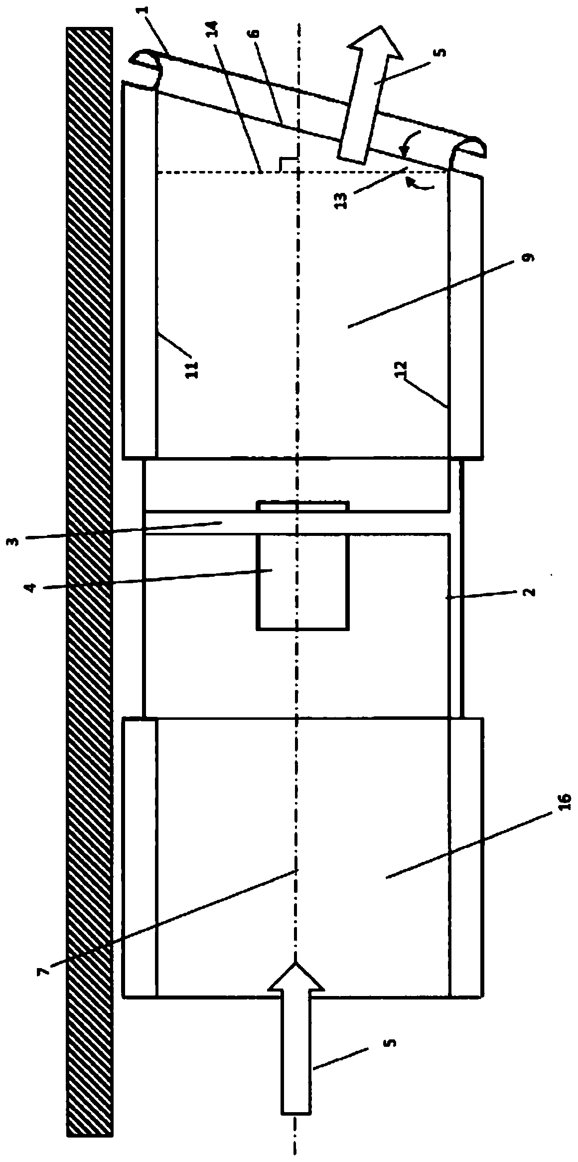
[0049] refer to figure 1 , figure 1 Shown is a cross-sectional side view of an embodiment of the present invention installed within a two-way ventilation device under a tunnel soffit, the two-way ventilation device being designed to operate in a fully reversible manner.

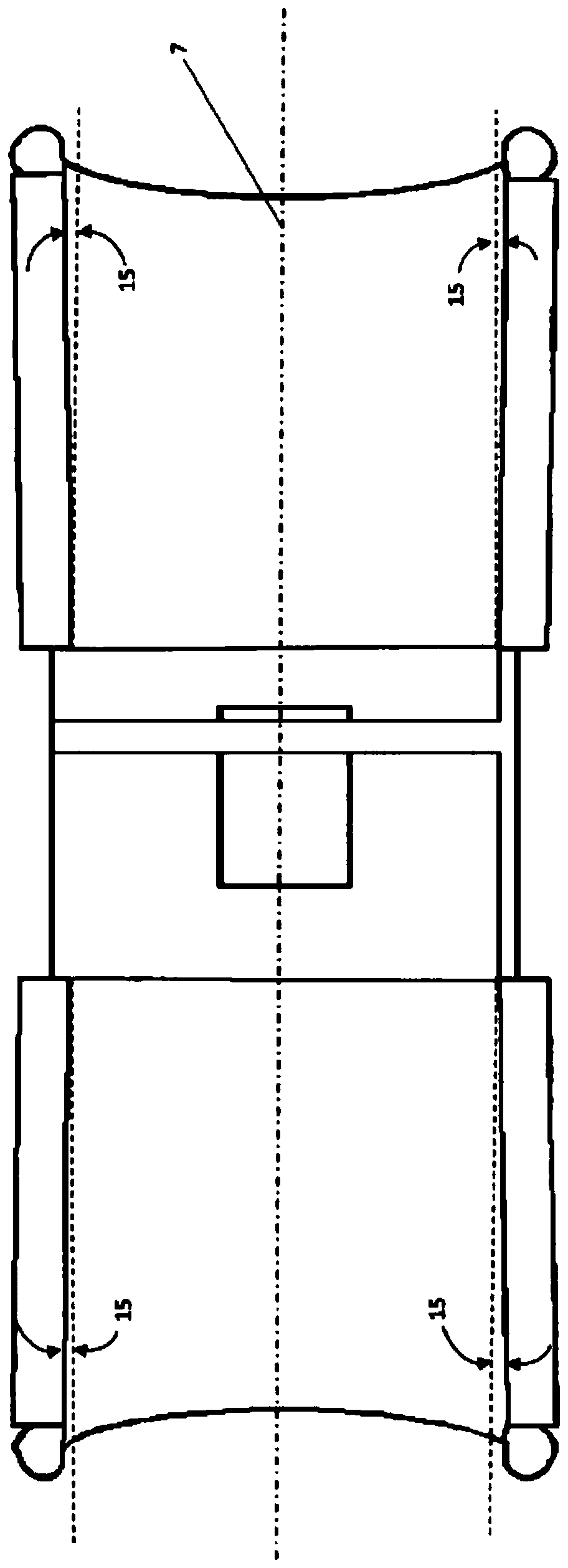
[0050] In this embodiment, a fan assembly including a fan rotor (3) driven by a motor (4) is mounted within the fan housing (2). The fan rotor (3) is installed along the centerline (7) of the fan.

[0051] The airflow (5) enters the fan rotor (3) through the bell mouth (1) and the inlet nozzle through hole (8), and then is discharged through the outlet nozzle through hole (9) and the bell mouth (1). The inlet and outlet trailing edges of the nozzle (6) are inclined at an angle (13) relative to the normal to the centerline (7) of the fan. The exhaust air flow is deflected by the upper surface of the bell mouth (1) in a direction away from the tunnel surface, thus reducing the Coanda effect.

[0052] Prefer...


PUM


Abstract

A ventilation device that enhances the effective longitudinal thrust of a fan assembly installed within a tunnel or other internal space. The nozzle trailing edge (6) is tilted so that it forms an angle (13) with respect to the fan centreline (7), with the surface of the nozzle throughbore being non-cylindrical in shape. The discharged flow (5) is turned away from the surrounding surfaces by a convergent-divergent bellmouth (1).

Description

Background technique [0001] Longitudinal ventilation with jet fans is a well-established technology used to create airflow in tunnels and car parks to improve air quality during normal and congested operations, and for smoke control during fires. [0002] A prior patent application number GB2512181 filed by the present applicant describes an improved jet fan in which the angle between the trailing edge of the nozzle and the centerline of the nozzle is non-perpendicular and in which at least one nozzle through-hole edge Arranged to divert the ventilation flow away from the surrounding tunnel surface. Said invention reduces the Coanda effect of the spray from the jet fan, thereby improving the energy efficiency of tunnel ventilation. [0003] Sloping one of the nozzle through-hole edges in GB2512181 to keep the ventilation flow away from the surrounding tunnel surface has the following effect: the trailing edge of the nozzle must be inclined at a large angle (approximately 30°)...

Claims


Application Information

Patent Timeline
Patent Type & Authority Applications(China)
IPC IPC(8): F04D29/44E21F1/00E21F1/08F04D29/54F04D25/08F04D29/60
CPCF05D2250/52E21F1/00F04D25/08F04D29/441F04D29/545F04D29/547F04D29/602E21F1/003
Inventor F·塔拉达
Owner MOSEN
Learn More