
Lens device and method for manufacturing lens device

A lens and lens body technology, applied in installation, telescope, optics, etc., can solve the problems of small size, system tube manufacturing cost, expensive, etc., and achieve the effect of cheap manufacturing, saving manufacturing cost, and efficient layout

Pending Publication Date: 2020-11-17
SCHOLLY FIBEROPTIC
View PDF0 Cites 0 Cited by
  • Summary
  • Abstract
  • Description
  • Claims
  • Application Information

AI Technical Summary

Problems solved by technology

[0004] It has been found that the production of such system pipes is very complicated and expensive, because on the one hand the spacer sleeves have to be produced with very high precision, but are very small in size and very thin-walled, and on the other hand because the spacer sleeves must be pushed through the entire system tube into its working position
[0005] In known lens arrangements, another disadvantage is that the spacer sleeve cuts the light path and thus vignetts the image

Method used


Image

  • Lens device and method for manufacturing lens device
  • Lens device and method for manufacturing lens device
  • Lens device and method for manufacturing lens device

Examples


Embodiment Construction

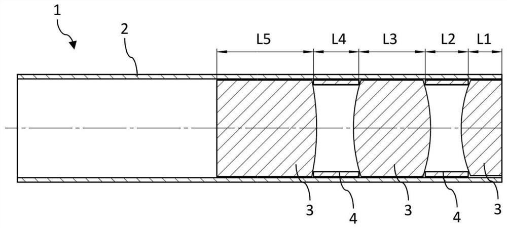
[0063] FIG. 1 shows a lens arrangement 1 according to the prior art. The lens arrangement 1 has an optics carrier 2 , which is designed here as a system tube. The optics carrier 2 is of tubular design. Three lenses 3 are arranged in the optics carrier 2 , wherein in each case a spacer ring 4 is arranged between the lenses 3 , around which spacer rings the axial position of the lenses 3 is defined. In this case, a rod lens is formed by way of example as lens 3 , but the invention is suitable for all lens forms without exception.

[0064] The position of the third lens 3 is obtained, for example, by adding the dimensions L1 to L4. From this it is clear that tolerances in the lengths of the spacer ring 4 and of the lens 3 accumulate. It is therefore almost impossible to determine the absolute position of the lens. This causes aberrations.

[0065] Also in the following embodiments, the lenses 3 are respectively shown as rod lenses. However, the invention is not limited to r...


PUM


Abstract

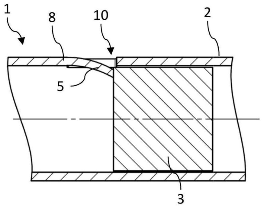
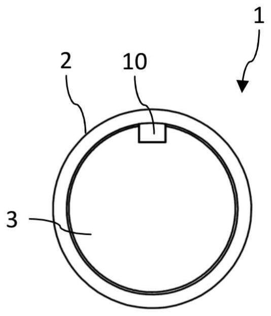
The invention relates to a lens device (1) for a rigid endoscope, comprising a tubular optical carrier (2), for example a system tube, and at least one lens (3), which is arranged in the optical carrier (2). The lens (3) is fastened within the optical carrier (2) by means of at least one axial stop (10). The axial stop (10) is formed by deformation of the optics carrier (2).

Description

technical field [0001] The invention relates to a lens arrangement having at least one lens and a tubular optics carrier in which the lens is arranged. Background technique [0002] Such lens arrangements are known and are used, for example, in rigid endoscopes. [0003] In the prior art, for example, system tubes are known as optics carriers, into which one or more lenses are inserted. So-called spacer sleeves are arranged between the individual lenses, which hold the lenses in the desired position. [0004] It has been found that the production of such system pipes is very complicated and expensive, because on the one hand the spacer sleeves have to be produced with very high precision, but are very small in size and very thin-walled, and on the other hand because the spacer sleeves It must be pushed through the entire system tube into its working position. [0005] A further disadvantage in known lens arrangements is that the spacer sleeve cuts the beam path and thus v...

Claims


Application Information

Patent Timeline
Patent Type & Authority Applications(China)
IPC IPC(8): G02B23/24G02B7/02
CPCG02B23/2476G02B7/02G02B7/021G02B7/025
Inventor M·格恩P·利贝特劳特S·施伦克尔
Owner SCHOLLY FIBEROPTIC
Learn More