Cooling device for food
A cooling device and food technology, which is applied to household refrigeration devices, food preservation, meat/fish preservation by freezing/cooling, etc., can solve the problem of insufficient cooling of hairy belly, etc., and achieve the effect of increasing the amplitude and good effect.
- Summary
- Abstract
- Description
- Claims
- Application Information
AI Technical Summary
Problems solved by technology
Method used
Image
Examples
Embodiment 1
[0024] Such as figure 1 As shown, a food cooling device includes a water tank 4, the top of the water tank 4 is open, the left end is an inlet, and the right end is an outlet. Feed plate 1 is installed obliquely downward at water tank 4 feed openings, and the high end of feed plate 1 is positioned at water tank 4 left ends. A discharge plate 6 is installed obliquely upwards at the discharge port of the water tank 4, and the high end of the discharge plate 6 is located at the right end of the water tank 4. A number of spray pipes 3 are installed horizontally on the upper part of the water tank 4, and no spray pipe 3 is provided above the feed plate 1 and the discharge plate 6. Both ends of each spray pipe 3 are connected to the two inner walls of the water tank 4, and the ends of all the spray pipes 3 are externally connected to a water pump through a connecting pipe to provide water.
[0025] The conveyer belt 2 that is used to convey hairy tripe is installed in the tank 4, ...
Embodiment 2
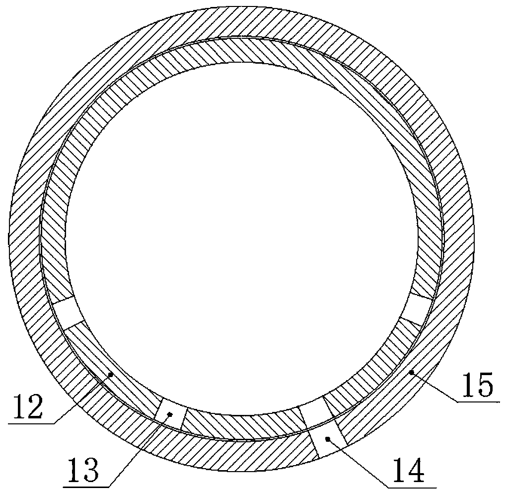
[0029] Such as figure 2 As shown, the difference between the present embodiment and the first embodiment is that an overturn mechanism for driving the tripe to overturn is installed in the water tank 4 . The overturning mechanism includes a jacking piece welded on the bottom plate in the middle of the water tank 4 for jacking up the conveyor belt 2, the jacking piece is located below the conveyor belt 2, that is, the conveyor belt 2 is laid on the jacking piece. In this embodiment, the jacking member adopts jacking rollers 11 , and the jacking rollers 11 are arranged along the width direction of the water tank 4 , that is, the two ends of the jacking rollers 11 are connected with the two side walls of the water tank 4 . Of course, a jacking plate with a triangular cross-section or a jacking structure of other shapes can also be used. When a jacking plate is used, the top of the jacking plate should have a circular arc transition to reduce friction with the conveyor belt 2 . ...
Embodiment 3
[0040] The difference between this embodiment and embodiment two is that some water spray pipes are installed inside the front and rear side walls of the water tank 4, and the nozzles of the water spray pipes are located in the chute (there is no protruding chute, which does not affect the pressing plate 8 sliding), the vertical sliding connection in the chute is connected with a sealing plate, and the sealing plate is connected with the pressing plate 8.
[0041] Initially, the mouth of the water spray pipe was blocked by the sealing plate, and the water in it could not be sprayed out. When the pressing plate 8 moves up and down, it can drive the sealing plate to slide up and down in the chute, thereby exposing the water spray pipe. In the water spray pipe, the water flow impacts the tripe, which can make the tripe close to the front and rear side walls of the water tank 4 move to the middle part of the water tank 4, avoiding the tripe and the side walls of the water tank 4 t...
PUM
 Abstract
Description
Claims
Application Information
 - R&D
- Intellectual Property
- Life Sciences
- Materials
- Tech Scout
- Unparalleled Data Quality
- Higher Quality Content
- 60% Fewer Hallucinations
Browse by: Latest US Patents, China's latest patents, Technical Efficacy Thesaurus, Application Domain, Technology Topic, Popular Technical Reports.
© 2025 PatSnap. All rights reserved.Legal|Privacy policy|Modern Slavery Act Transparency Statement|Sitemap|About US| Contact US: help@patsnap.com


