Novel heat exchanger impingement baffle

A technology of heat exchanger and anti-shock plate, which is applied in the direction of heat exchange equipment, heat exchanger shell, lighting and heating equipment, etc., can solve the problem of the loss of anti-shock effect of the anti-shock plate, the impact damage of the heat exchange tube, and the uneven distribution of fluid. and other problems, to achieve the effect of preventing falling off, reducing damage and simple structure

Pending Publication Date: 2020-02-04
YONGSHENG MACHINERY IND KUNSHAN
View PDF0 Cites 0 Cited by
  • Summary
  • Abstract
  • Description
  • Claims
  • Application Information

AI Technical Summary

Problems solved by technology

[0004] In the prior art, there are multiple rows of heat exchange tubes in the shell of the shell-and-tube heat exchanger, and the anti-shock plate installed at the entrance of the shell is shown in Figure (4), and the anti-shock plate is welded on the shell. Its main defects are: the area of ​​the anti-shock plate is too small; when the shell-side fluid enters, its direction is perpendicular to the anti-scourr plate, and the long-term high-speed movement of the fluid may easily cause the anti-scourr plate to fall off, causing the anti-scourr plate to lose its anti-shock On the other hand, after the anti-scouring plate is added, the fluid will be concentrated at both ends of the anti-scouring plate and enter the tube bundle area. The uneven distribution of the fluid will still cause impact damage to the heat exchange tube, and the pressure drop will increase. Vibration will inevitably lead to the impact of heat exchange tubes and baffle holes and be cut off

Method used


Image

  • Novel heat exchanger impingement baffle
  • Novel heat exchanger impingement baffle
  • Novel heat exchanger impingement baffle

Examples


Embodiment

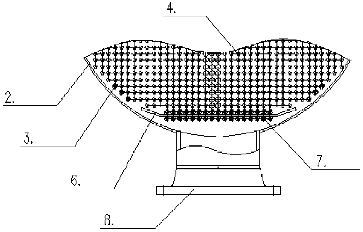
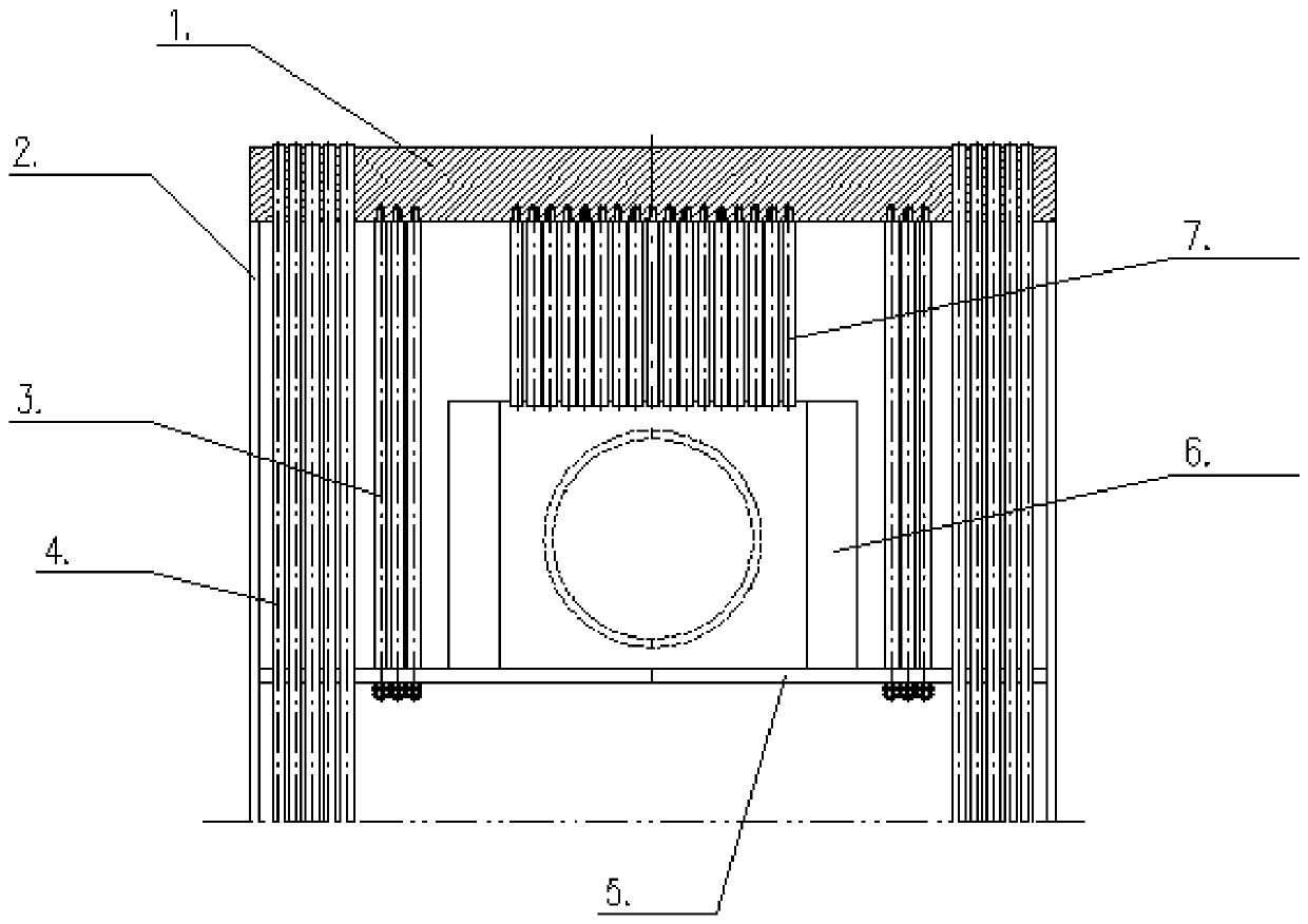
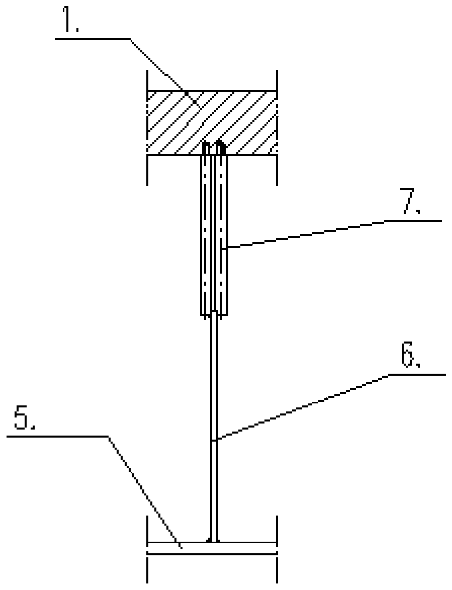
[0023] Such as Figure 1-3 As shown, a new type of heat exchanger anti-shock plate includes a tube plate 1, a shell-side cylinder 2 is provided at the lower end of the tube plate 1, and heat exchange tubes 4 are symmetrically arranged on both sides of the inner side of the shell-side cylinder 2, and the symmetrically arranged heat exchangers The side of the heat pipe 4 away from the shell body 2 is symmetrically provided with an anti-shock bar 3, and the lower end of the tube sheet 1 is provided with an anti-shock bar 7 between the two symmetrically arranged anti-shock bars 3, and the lower end of the anti-shock bar 7 An anti-shock plate 6 is provided, a baffle plate 5 is provided at the lower end of the anti-shock plate 6, and a medium inlet 8 is also provided on one side of the shell-side cylinder 2.

[0024] Preferably, the shell-side cylinder 2 is rectangular and covers the outside of the lower end of the tube sheet 1 , and the tube sheet 1 is circular.

[0025] Preferabl...


PUM


Abstract

The invention discloses a novel heat exchanger impingement baffle. The impingement baffle comprises a pipe plate. The lower end of the pipe plate is provided with a shell side cylinder, the two edgesof the inner side of the shell side cylinder are symmetrically provided with heat exchange pipes, and anti-impact check rods are symmetrically arranged on the sides, away from the shell side cylinder,of the symmetrically-arranged heat exchange pipes. An anti-impact rod is arranged on the portion, between the two symmetrically-arranged anti-impact check rods, of the lower end of the pipe plate, the lower end of the anti-impact rod is provided with an impingement baffle body, the lower end of the impingement baffle body is provided with a baffle plate, and one side of the shell side cylinder isfurther provided with a medium inlet. The novel heat exchanger impingement baffle has the advantages that after the impingement baffle is applied to a heat exchanger, fluid distribution is even, theimpingement baffle can be effectively prevented from falling off, wear and leakage of the heat exchange pipes are reduced, safe and reliable operation of the heat exchanger is guaranteed, and the service life of the heat exchanger is prolonged. The novel heat exchanger impingement baffle is simple in structure, reasonable in design and low in equipment cost and has a good anti-impact effect, and the impingement baffle does not need to be additionally welded.

Description

technical field [0001] The invention relates to the technical field of heat exchangers, in particular to a novel heat exchanger anti-shock plate. Background technique [0002] A heat exchanger is a device used to exchange heat from a medium, and it is widely used in chemical industry, petroleum, oil refining and many other industrial sectors. [0003] For heat exchangers, heat exchange tubes, tube sheets, equipment flanges, heads, shells, expansion joints, etc. are the main pressure components, while other components such as anti-shock devices are used as auxiliary components. In the design and manufacturing process, it is easy to ignore, so that the heat exchanger cannot achieve safe and reliable operation. The anti-shock problem of shell-and-tube heat exchangers has a long history. Setting a reasonable and effective anti-shock structure can prolong the use of the heat exchanger life. [0004] In the prior art, there are multiple rows of heat exchange tubes in the shell o...

Claims


Application Information

Patent Timeline
Patent Type & Authority Applications(China)
IPC IPC(8): F28F9/22F28F9/24
CPCF28F9/22F28F9/24F28F2009/224
Inventor 王建江谢金山陈伟锋谭雅丹
Owner YONGSHENG MACHINERY IND KUNSHAN
Why Eureka
Try Eureka