A bearing installation monitoring system for pump valves

A monitoring system and pump valve technology, applied in mechanical bearing testing, mechanical component testing, machine/structural component testing, etc., can solve problems such as not being in a straight line, affecting the rotation of the power shaft, and affecting the efficiency of pump and valve failure analysis , to achieve the effect of fast and convenient monitoring and accurate installation position

Active Publication Date: 2020-12-29
合肥华升泵阀股份有限公司
View PDF7 Cites 0 Cited by
  • Summary
  • Abstract
  • Description
  • Claims
  • Application Information

AI Technical Summary

Problems solved by technology

[0004] The purpose of the present invention is to provide a bearing installation monitoring system for pump valves. In order to overcome the above, according to the statistics of pump valve failures, the deviation of the bearing installation position causes pump valve failures, accounting for 60% of all pump valve failures. Above, solving the bearing installation offset is also the most important thing to solve the pump valve failure. At the same time, during the use process, the deviation of the bearing installation position will seriously affect the rotation of the power shaft, resulting in the rotation axes of the two ends of the power shaft not being in a straight line; Secondly, during the use of the pump valve, it is necessary to monitor the bearings in all directions. Otherwise, when the pump valve fails, it is necessary to detect and check the bearings in the pump valve, which will seriously affect the technical problem of the efficiency of pump valve failure analysis.

Method used


Image

  • A bearing installation monitoring system for pump valves
  • A bearing installation monitoring system for pump valves
  • A bearing installation monitoring system for pump valves

Examples


Embodiment Construction

[0035]The technical solutions of the present invention will be clearly and completely described below in conjunction with the embodiments. Apparently, the described embodiments are only some of the embodiments of the present invention, not all of them. Based on the embodiments of the present invention, all other embodiments obtained by persons of ordinary skill in the art without creative efforts fall within the protection scope of the present invention.

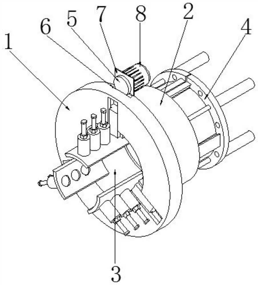
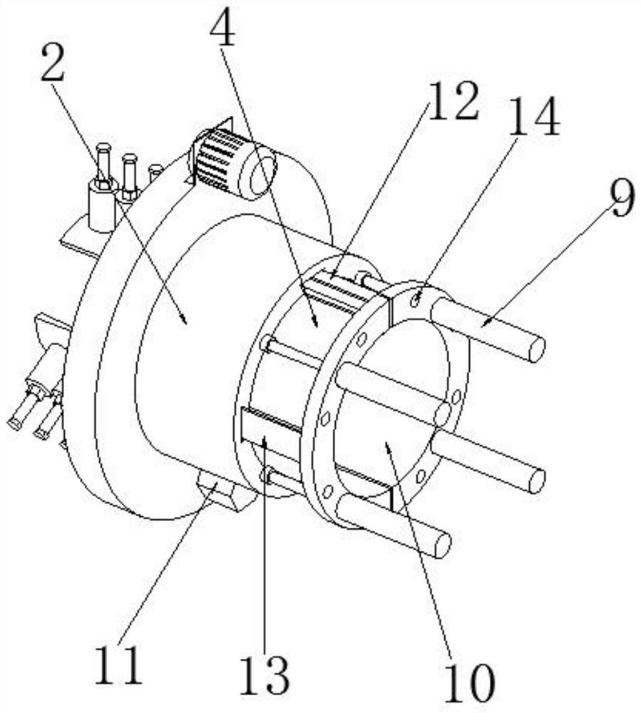
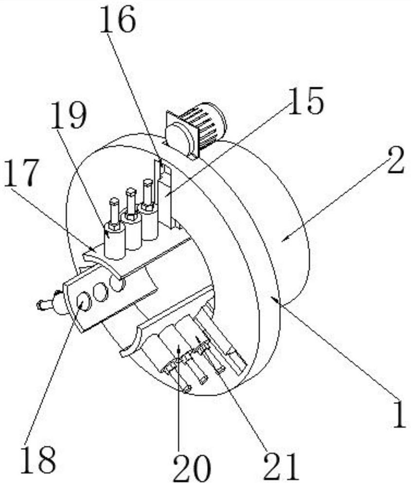
[0036] see Figure 1-7 As shown, a bearing installation monitoring system for pump valves includes an adjustment seat 1, a sleeve seat 2 and a card seat 4. A sleeve seat 2 is provided on one side of the adjustment seat 1, and a second set is provided on the inner side of the adjustment seat 1 and the sleeve seat 2. One set of slots 3, one end of the first set of slots 3 is fitted with two card holders 4;

[0037] A motor limit seat 7 is installed on the outside of the adjustment seat 1, and a servo motor 8 is fixedly instal...


PUM


Abstract

The present invention discloses a bearing installation monitoring system for a pump valve. The system comprises an adjusting base, a sleeve base and clamping bases, the sleeve base is arranged on oneside of the adjusting base, a first sleeve groove is formed in the inner side of the adjusting base and the inner side of the sleeve base, and the two clamping bases are arranged in one end of the first sleeve groove in a sleeved mode; according to the invention, the positions of the pump valve bearings in three directions are sensed by the phase sensors which are arranged at an angle of 120 degrees, when measurement data is the same or is within an allowable error range, the installation positions of the pump valve bearings are accurate, when the measurement data exceeds the allowable error range, the pump valve bearings are required to be reinstalled to rapidly and conveniently monitor the installation positions of the pump valve bearings, timely obtain monitoring information and avoid the problems occurring in the installation of the pump valve bearings, the bearing installation monitoring device can monitor installation, temperature and vibration of the pump valve bearings, guarantees mutual noninterference through the structural design of the device when monitoring the installation, temperature and vibration of the pump valve bearings, and can quickly, normally and conveniently complete monitoring of the pump valve bearing.

Description

technical field [0001] The invention relates to the field of bearing installation monitoring equipment, in particular to a bearing installation monitoring system for pump valves. Background technique [0002] Bearing is an important part of contemporary mechanical equipment. Its main function is to support the mechanical rotating body, reduce the friction coefficient during its movement, and ensure its rotation accuracy; while the bearing in the pump valve is to support the rotating shaft and The structure that guarantees its rotation accuracy plays a vital role in the use of pump valves. [0003] According to the statistics of pump and valve faults, it is found that the fault of the pump and valve caused by the deviation of the bearing installation position accounts for more than 60% of all the faults of the pump and valve. During the process, the deviation of the bearing installation position will seriously affect the rotation of the power shaft, causing the rotation axes...

Claims


Application Information

Patent Timeline
Patent Type & Authority Patents(China)
IPC IPC(8): G01B21/00G01M13/04G01D21/02
CPCG01B21/00G01D21/02G01M13/04G01M13/045
Inventor 柴立平尹来弟徐峰邓业稳许允宫克
Owner 合肥华升泵阀股份有限公司
Why Eureka
Try Eureka