Fiber optic acoustic wave sensing cross-dipole acoustic wave well-logging system and measurement method thereof

A dipole acoustic wave, acoustic wave sensing technology, applied in the field of geophysical exploration, can solve problems such as inability to work for a long time

Pending Publication Date: 2020-02-04
OPTICAL SCI & TECH (CHENGDU) LTD
View PDF0 Cites 10 Cited by
  • Summary
  • Abstract
  • Description
  • Claims
  • Application Information

AI Technical Summary

Problems solved by technology

[0007] The current downhole orthogonal dipole array acoustic logging tools use dipole or multipole piezoelectric acoustic transducers to receive acoustic waves (longitudinal waves, shear waves, Stoneley waves) in different directions in the borehole. , dipole or multipole piezoelectric acoustic transducers and their supporting amplifiers, analog-to-digital conversion and data storage devices, and downhole data transmission modules cannot work for a long time in a high temperature environment (deep well)
In addition, since the downhole orthogonal dipole array acoustic logging instruments are currently electronic instruments, the downhole data transmission module still cannot solve the bottleneck problem of real-time transmission of downhole big data to the control computer in the wellhead logging vehicle at high speed.

Method used


Image

  • Fiber optic acoustic wave sensing cross-dipole acoustic wave well-logging system and measurement method thereof
  • Fiber optic acoustic wave sensing cross-dipole acoustic wave well-logging system and measurement method thereof
  • Fiber optic acoustic wave sensing cross-dipole acoustic wave well-logging system and measurement method thereof

Examples


Embodiment Construction

[0048] The present invention will be further described below in conjunction with the accompanying drawings and specific embodiments.

[0049] The specific embodiments of the present invention are described below so that those skilled in the art can understand the present invention, but it should be clear that the present invention is not limited to the scope of the specific embodiments. For those of ordinary skill in the art, as long as various changes Within the spirit and scope of the present invention defined and determined by the appended claims, these changes are obvious, and all inventions and creations using the concept of the present invention are included in the protection list.

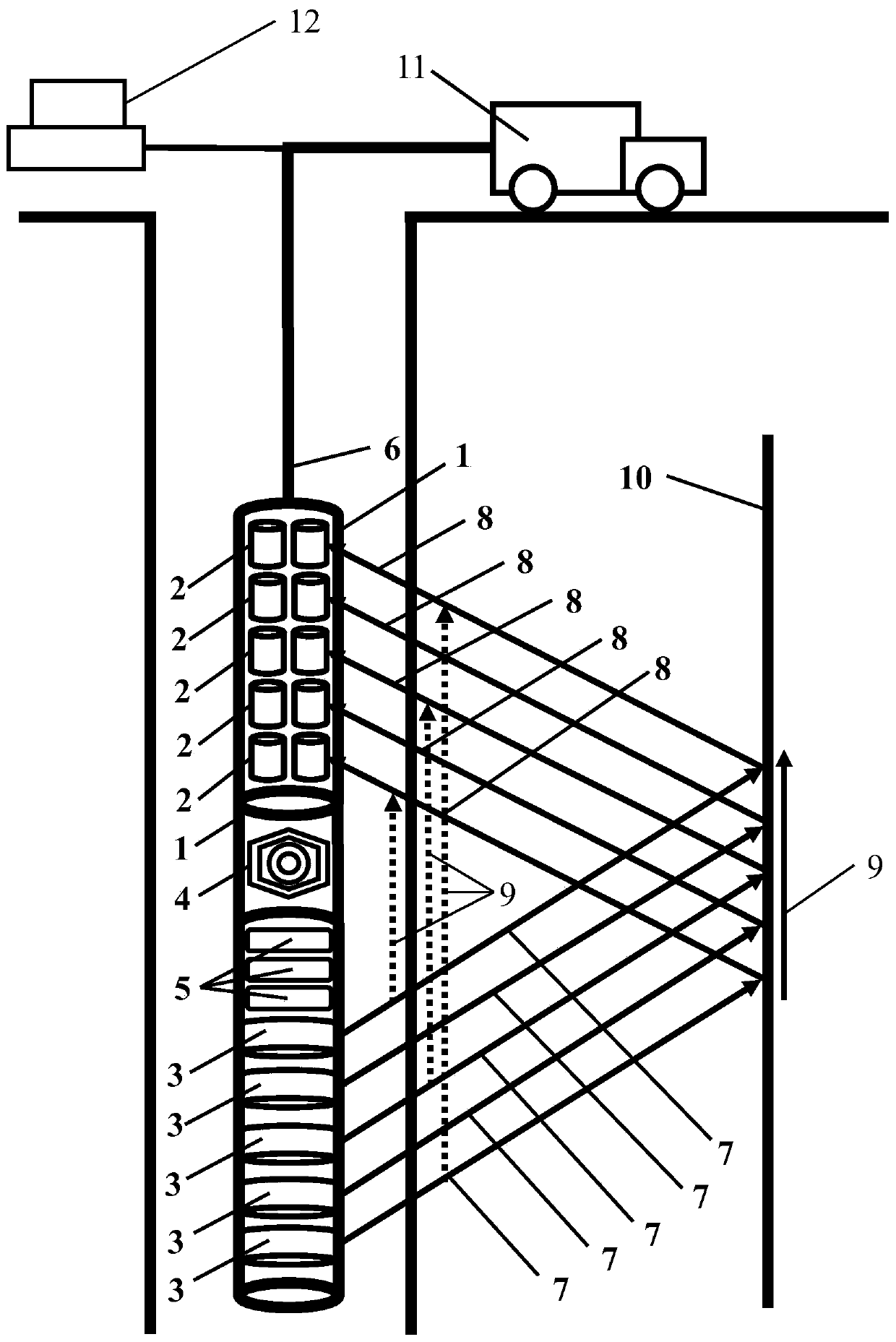
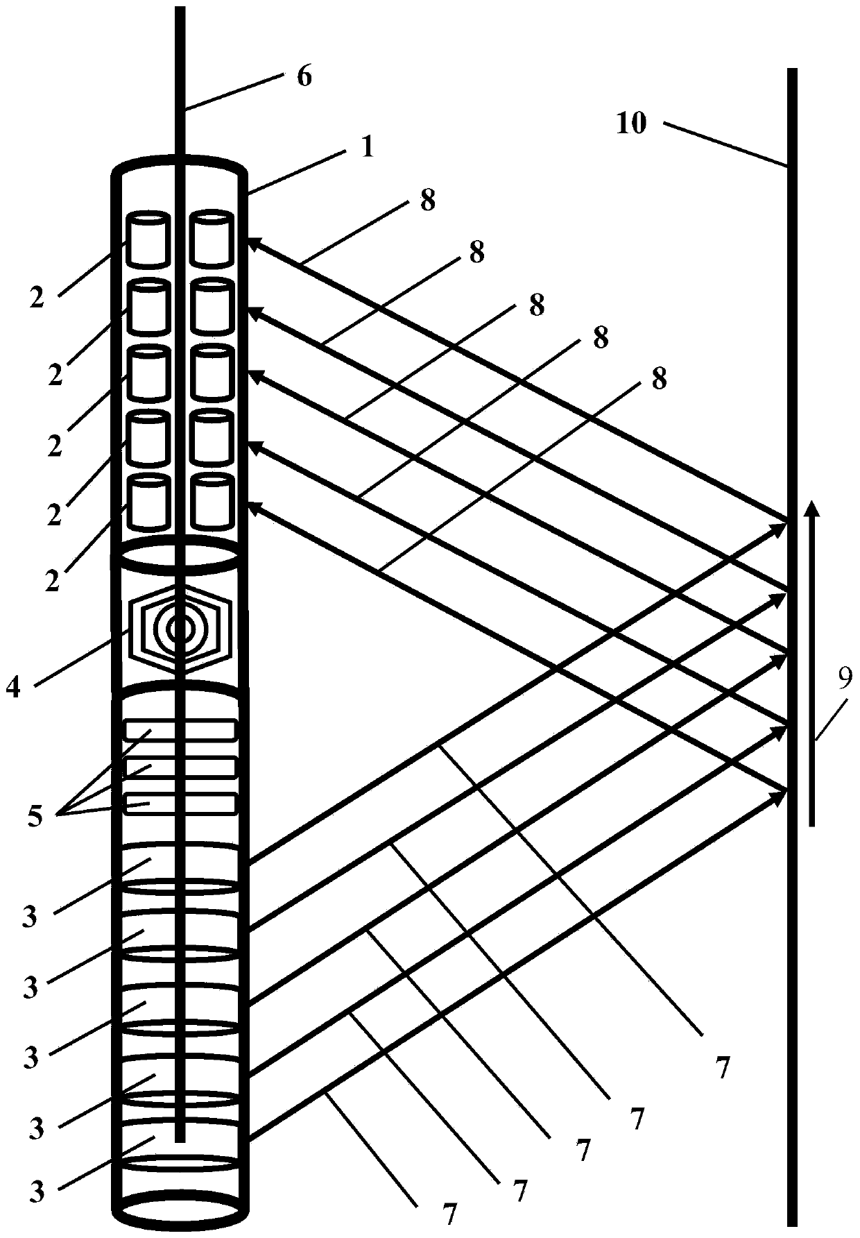
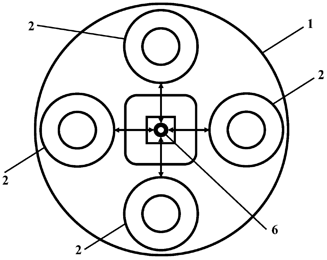
[0050] Such as figure 1 As shown, the optical fiber acoustic wave sensing orthogonal dipole acoustic logging system includes an optical fiber acoustic wave sensing orthogonal dipole acoustic logging device in the well, a ground wellhead logging vehicle 11, and a ground DAS modulation and dem...


PUM


Abstract

The invention provides a fiber optic acoustic wave sensing cross-dipole acoustic wave well-logging system and a measurement method thereof. The fiber optic acoustic wave sensing cross-dipole acousticwave well-logging system comprises an in-well fiber optic acoustic wave sensing cross-dipole acoustic wave well-logging device, the in-well fiber optic acoustic wave sensing cross-dipole acoustic wavewell-logging device comprises a cylindrical structure instrument shell and a fiber optic acoustic wave dipole sensor; and a fiber optic gyroscope, a sound insulation body short section and a dipole acoustic source generator are perpendicularly and sequentially mounted on the lower part of the fiber optic acoustic wave dipole sensor. A ground wellhead well-logging vehicle controls going down intoa well and rising from the well of the in-well fiber optic acoustic wave sensing cross-dipole acoustic wave well-logging device, provides a power supply for the in-well fiber optic acoustic wave sensing cross-dipole acoustic wave well-logging device, and drives the dipole acoustic source generator to continuously and repeatedly emit a dipole acoustic wave signal during operation; and a ground DASmodulation and demodulation instrument emits a laser pulse into the fiber optic acoustic wave dipole sensor, and collects a backscattering rayleigh wave inside the fiber optic acoustic wave dipole sensor. The fiber optic acoustic wave sensing cross-dipole acoustic wave well-logging system can work for a long time at the high temperature and realize the function of high-speed upward-transmission ofdata.

Description

technical field [0001] The invention relates to the technical field of geophysical exploration, in particular to an optical fiber acoustic wave sensing orthogonal dipole acoustic logging system and a measurement method thereof. Background technique [0002] Acoustic logging refers to a logging method that uses different acoustic characteristics such as speed, amplitude and frequency changes when sound waves propagate in different rocks to study the geological section of drilling and judge the quality of cementing. Sonic logging is a logging method that determines the properties of rock formations by studying the propagation speed of sound waves in rock formations in boreholes. Commonly used sonic velocity logging tools include a sonic generator (T) and two receivers (R., R 1 ). The recorded parameter is the time difference (Δt) between the arrival of the sound wave at the two receivers, ie the time it takes for the sound wave to travel through the rock formation between th...

Claims


Application Information

Patent Timeline
Patent Type & Authority Applications(China)
IPC IPC(8): G01V1/42E21B47/14
CPCE21B47/14G01V1/42G01V2210/1429
Inventor 余刚王熙明夏淑君王秀明
Owner OPTICAL SCI & TECH (CHENGDU) LTD
Why Eureka
Try Eureka