Automatic timed irrigation device for agricultural production

An automatic irrigation and agricultural technology, which is applied in drinking water devices, agriculture, water supply devices, etc., can solve problems such as the inability to use rainwater reasonably and effectively, the death of crops due to drought, and the inability to irrigate agricultural products, so as to meet irrigation needs, make full and reasonable use, The effect of reducing labor intensity

Inactive Publication Date: 2020-02-07
裴文超
View PDF13 Cites 12 Cited by
  • Summary
  • Abstract
  • Description
  • Claims
  • Application Information

AI Technical Summary

Problems solved by technology

[0003] The existing irrigation of agricultural products generally adopts the method of artificial irrigation. The farmers themselves connect the water spray pipe to the water source, and hold the water spray pipe to place the nozzle in the farmland to realize farmland irrigation. This irrigation method is not only labor-intensive, but also When managers go out for business, they cannot irrigate the agricultural products in time. At the same time, when the phenomenon of water loss in agricu

Method used


Image

  • Automatic timed irrigation device for agricultural production
  • Automatic timed irrigation device for agricultural production

Examples


Embodiment 1

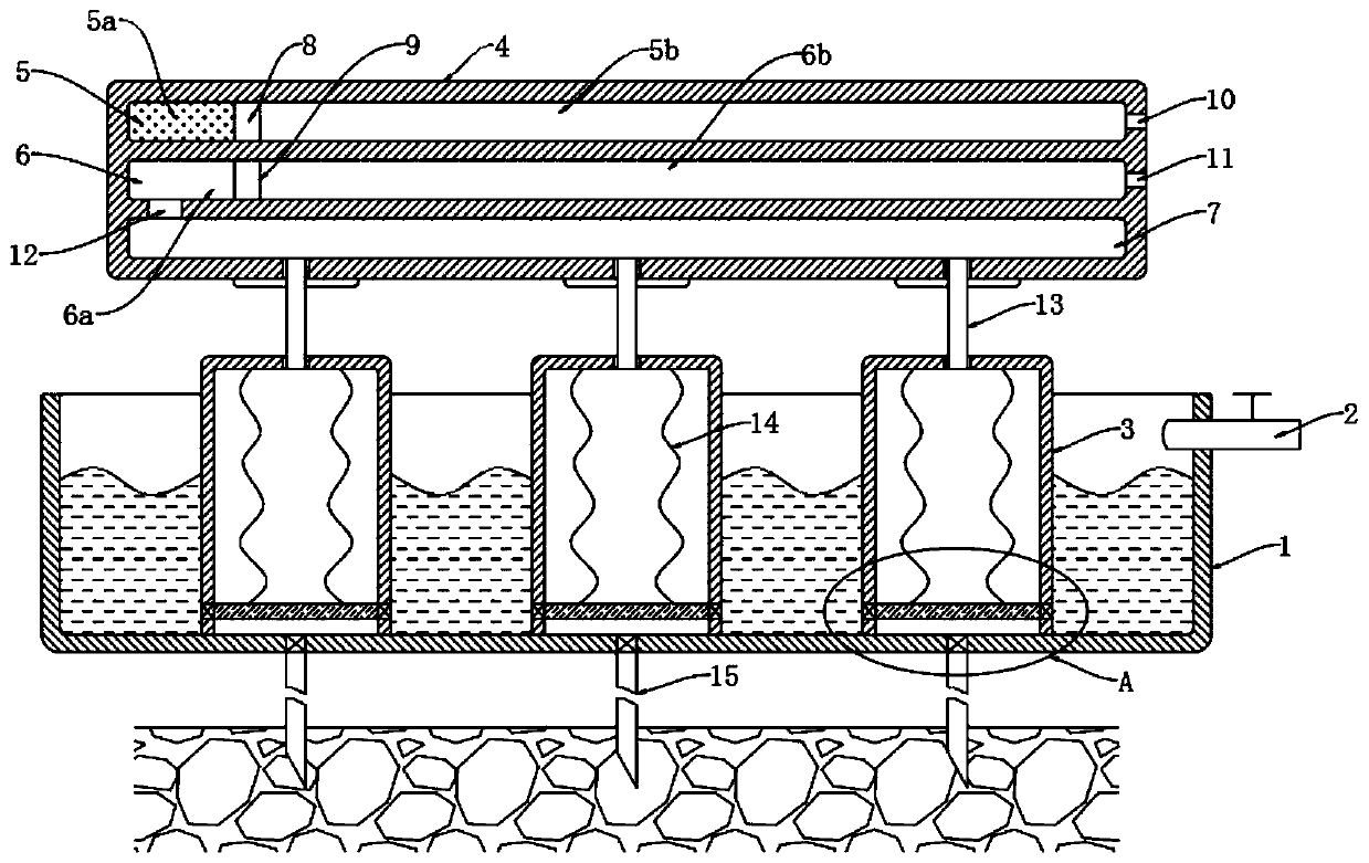
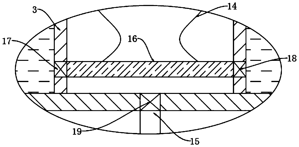
[0019] refer to Figure 1-2 , a timing automatic irrigation device for agricultural production, comprising a water storage tank 1 and a sun visor 4, the upper end of the side wall of the water storage tank 1 is connected with a water inlet pipe 2, and the inner bottom of the water storage tank 1 is uniformly equipped with a water collection cover 3 with an inverted buckle. The first slide chamber 5, the second slide chamber 6 and the third slide chamber 7 are opened in the sun visor 4 from top to bottom in sequence, and the ends of the sun visor 4 are provided with air ducts 13 communicating with the upper end of the water collecting cover 3 , the upper end of the air duct 13 communicates with the third sliding cavity 7, the first sliding cavity 5 and the second sliding cavity 6 are respectively sealed and slidably connected with a first magnetic block 8 and a second magnetic block 9, and the first magnetic block 8 connects the first magnetic block to the second sliding cavity....

Embodiment 2

[0028] The difference from Embodiment 1 is that the shape of the sun visor 4 is a roof shape with a high middle and low sides, and the length of the water storage tank 1 is greater than that of the sun visor 4 .

[0029] In this embodiment, it is ensured that in rainy weather, the rainwater falling on the upper end of the sun visor 4 can flow into the water storage tank 1 along the sun visor 4 for storage, so that the rainwater can be used reasonably and effectively, which can not only avoid the loss of agricultural products during the rainy season. The phenomenon of waterlogging caused by too much water can make full use of rainwater, irrigate agricultural products when needed, and save water resources.


PUM

PropertyMeasurementUnit
Boiling pointaaaaaaaaaa

Abstract

The invention discloses an automatic timed irrigation device for agricultural production, comprising a water storage tank and a sunshade, wherein a water inlet pipe is communicated to the upper end ofthe side wall of the water storage tank, water collecting hoods which are inverted are uniformly distributed in the bottom of the water storage tank, and a first slide cavity, a second slide cavity and a third slide cavity are sequentially formed in the sun shade from top to bottom sequentially. With the arrangement of the water storage tank, the sun shade, the water collecting hoods, first magnets and second magnets, evaporated liquid absorbs heat to evaporate gradually along with temperature rising in the morning, the first magnets drive the second magnets to slide to extract air in the upper ends of the water collecting hoods to form negative pressure, and then water is pumped in the water collecting hoods; the evaporated liquid is cooled and liquified with temperature reducing in theevening, the first magnets drive the second magnets to reset, water in the water collecting hoods is squeezed out from a water conduit so as to realize automatic irrigation to crops in the evening; meanwhile, rainwater can be collected for irrigation as needed, and thus, irrigation is much reasonable.

Description

technical field [0001] The invention relates to the field of agricultural irrigation, in particular to a timing automatic irrigation device for agricultural production. Background technique [0002] In agricultural production, irrigation is a very important task. Under natural conditions, the water requirements of agricultural products cannot be met due to insufficient or uneven distribution of precipitation. To make up for the lack of natural rainfall, so as to ensure the normal growth of crops and obtain high and stable yields. [0003] The existing irrigation of agricultural products generally adopts the method of artificial irrigation. The farmers themselves connect the water spray pipe to the water source, and hold the water spray pipe to place the nozzle in the farmland to realize farmland irrigation. This irrigation method is not only labor-intensive, but also When managers go out for business, they cannot irrigate the agricultural products in time. At the same time,...

Claims


Application Information

Patent Timeline
IPC IPC(8): A01G25/00E03B3/02
CPCA01G25/00E03B3/02Y02A20/108
Inventor 裴文超
Owner 裴文超
Why Eureka
Try Eureka