Box-type transformer

A box-type transformer and a technology for transformers, applied in the field of transformers, can solve the problems that the component temperature affects the normal operation of the transformer, shorten the service life of the box-type transformer, and damage the box-type transformer, achieve high cooling and dehumidification efficiency, achieve energy-saving effects, and increase use. effect of life

Inactive Publication Date: 2020-02-07
JIANGSU HAIKAI ELECTRIC
View PDF0 Cites 0 Cited by
  • Summary
  • Abstract
  • Description
  • Claims
  • Application Information

AI Technical Summary

Problems solved by technology

However, the single heat dissipation method in the prior art is likely to cause heat dissipation dead angles, resulting in excessive temperature of some components and affecting the normal operation of the transformer
Moreover, the box-type transformer is installed outside during use. When a large pressure acts on the surface of the box-type transformer, because the shock absorption effect of the existing box-type transformer is poor, when the surface suffers a large When the pressure is high, it is easy to cause damage to the box-type transformer and shorten the service life of the box-type transformer

Method used


Image

  • Box-type transformer
  • Box-type transformer
  • Box-type transformer

Examples


Embodiment 1

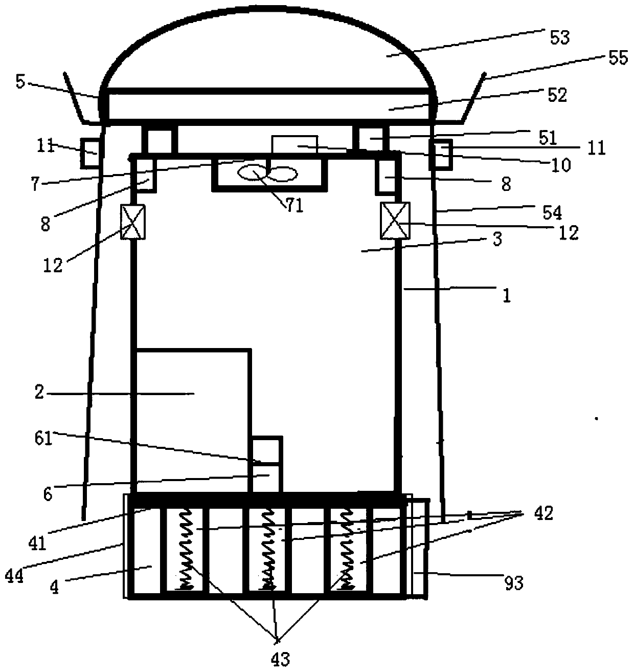
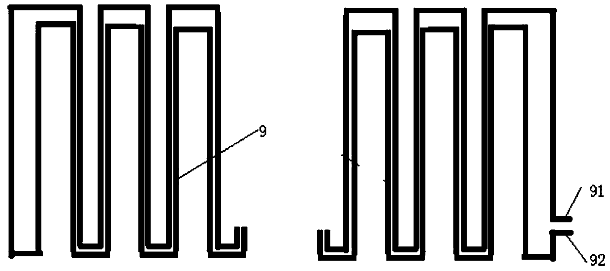
[0021] Such as figure 1 , figure 2 As shown, a box-type transformer includes a box-type transformer main body 1. The box-type transformer body 1 includes a control room 2, a component room 3 and an installation base 4. The component room includes a top plate, and the top plate is provided with There is rainproof cover 5, and described rainproof cover comprises connecting bracket 51, connecting plate 52, arc rain shielding cover 53 and side plate 54, and described connecting bracket is arranged on top board, and described connecting bracket connects top board and A connecting plate, an arc-shaped rain cover 53 is arranged above the connecting plate, and a side plate is arranged below the connecting plate, and the side plate is set as a baffle plate in the style of a louver, and the side plate is provided with an anti- Hit the rubber bump, the side plates are arranged on both sides and the back of the box-type transformer; the lower right side of the control room is provided w...


PUM


Abstract

The invention discloses a box-type transformer. The box-type transformer comprises a box-type transformer main body 1; a component chamber comprises a top plate; a rainproof shield 5 is arranged on the top plate; the rainproof shield comprises a connecting support 51, a connecting plate 52, an arc-shaped rain shielding cover 53 and a side square plate 54; the connecting support is arranged above the top plate; the connecting support is connected with the top plate and the connecting plate through bolts; the arc-shaped rain shielding cover 53 is arranged above the connecting plate; the side square plate is arranged below the connecting plate; the side square plate is arranged to be a shutter-shaped partition plate; anti-collision rubber protrusions are arranged on the side square plate; theside square plate is arranged on the two side faces and the rear face of the box-type transformer; a tool containing chamber 6 is arranged on the lower right side of the control chamber and providedwith an insulating partition plate 61, and a heat dissipation pipe (9) is arranged on the inner side wall of the transformer main body 1; and a fan placement chamber 7 is arranged above the box-type transformer main body, a cooling fan 71 is installed in the fan placement chamber and fixedly connected with the top plate, and four LED lamps 8 are symmetrically arranged at the four corners of the upper portion of the box-type transformer main body.

Description

technical field [0001] The invention relates to the technical field of transformers, in particular to a box-type transformer. Background technique [0002] The box-type transformer is a traditional transformer designed in a box-type housing. It has the advantages of small size, light weight, low noise, and low power consumption. It adopts a fully enclosed structure, compact structure, and beautiful appearance design. It is widely used in Factories, mines, enterprises, schools, residential areas and commercial centers and other places. However, the single heat dissipation method in the prior art may easily cause heat dissipation dead angles, resulting in overheating of some components and affecting the normal operation of the transformer. Moreover, the box-type transformer is installed outside during use. When a large pressure acts on the surface of the box-type transformer, because the shock absorption effect of the existing box-type transformer is poor, when the surface su...

Claims


Application Information

Patent Timeline
Patent Type & Authority Applications(China)
IPC IPC(8): H01F27/00H01F27/02H01F27/06H01F27/08H01F27/40
CPCH01F27/00H01F27/008H01F27/02H01F27/06H01F27/085H01F27/402H01F2027/406
Inventor 戴敏
Owner JIANGSU HAIKAI ELECTRIC
Why Eureka
Try Eureka