Bundling device for fuel cell stack
A technology for fuel cell stacks and strapping devices, which is applied to fuel cells, circuits, electrical components, etc., and can solve problems such as uneven fastening force and poor stability
- Summary
- Abstract
- Description
- Claims
- Application Information
AI Technical Summary
Problems solved by technology
Method used
Image

Examples
Embodiment 1
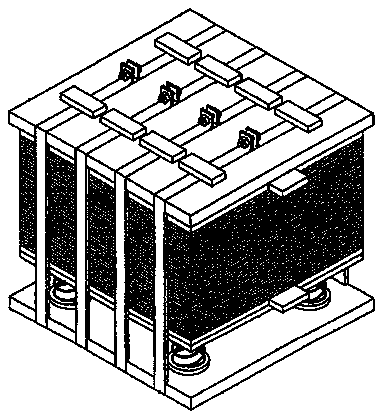
[0087] The embodiment of the present invention proposes a bundling device for a fuel cell stack. Compared with other embodiments of the present invention, the embodiment of the present invention has its common core features, such as Pic 4-1 with Figure 4-2 As shown, it includes a drawstring 1 and a drawstring locking device 2, specifically:
[0088] The strap locking device 2 includes at least two threaded locking pieces 21 and a base 22, and the at least two threaded locking pieces 21 are arranged on the base 22 in a rotating shaft manner; Among them, it is preferable to use the belt locking device 2 composed of two locking parts 21. The reason is that it is difficult to synchronize, and the width of the belt 1 designed in this way can meet the requirements of most scenarios. According to experience , Utilize two locking parts 21 to form the strap locking device that can support the strap model with a width of 3-5cm. In the actual implementation process, application scena...
Embodiment 2
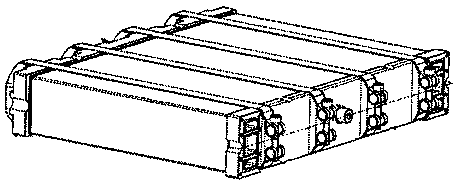
[0103] The proposal of the embodiment of the present invention is based on the structure of the base 22 proposed in Embodiment 1, which is respectively used to fix the second end 13 of the strap 1 and the structure of the first end 12 used to introduce the strap 1, and proposes a Specific and feasible implementation methods. It should be pointed out that the embodiment of the present invention is an example of a specific coupling structure between the belt 1 and the belt locking device 2 in the first embodiment. The content of each extension solution in Embodiment 1 is combined accordingly, and details will not be described later.
[0104] In the embodiment of the present invention, such as Figure 5-1 with Figure 5-2 As shown, on the side base 22 provided with the protrusion 223, after the corresponding bearing rod 23 is pushed into the chute 222, the bottom of the bearing rod 23 and the protrusion 223 are separated by an accommodation belt 1 The space height d2, so that ...
Embodiment 3
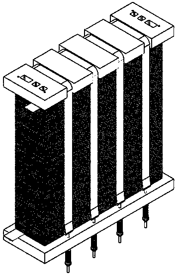
[0109] The proposal of the embodiment of the present invention is based on the structure of the base 22 proposed in Embodiment 1, which is respectively used to fix the second end 13 of the strap 1 and the structure of the first end 12 used to introduce the strap 1, and proposes a Specific and feasible implementation methods. It should be pointed out that the embodiment of the present invention is an example of a specific coupling structure between the belt 1 and the belt locking device 2 in the first embodiment. The content of each extension solution in Embodiment 1 is combined accordingly, and details will not be described later. Under a certain application scenario, the structure proposed in the embodiment of the present invention can have a more stable effect than that in the second embodiment.
[0110] Such as Figure 6-1 with Figure 6-2 shown, where Figure 6-1 It is the front view after the first locking member 211 and the belt 1 are hidden after being sectioned thr...
PUM
 Abstract
Description
Claims
Application Information
 - R&D
- Intellectual Property
- Life Sciences
- Materials
- Tech Scout
- Unparalleled Data Quality
- Higher Quality Content
- 60% Fewer Hallucinations
Browse by: Latest US Patents, China's latest patents, Technical Efficacy Thesaurus, Application Domain, Technology Topic, Popular Technical Reports.
© 2025 PatSnap. All rights reserved.Legal|Privacy policy|Modern Slavery Act Transparency Statement|Sitemap|About US| Contact US: help@patsnap.com