
Transient voltage control method

A technology for transient voltage control and transient voltage stabilization, applied in the field of transient voltage control, can solve the problems of structural stability changes, the need for improvement of nonlinear dynamic methods, and the difficulty in determining critical energy, so as to meet the requirements of voltage stability. Effect

Pending Publication Date: 2020-02-07
NORTH CHINA ELECTRIC POWER UNIV (BAODING)
View PDF3 Cites 8 Cited by
  • Summary
  • Abstract
  • Description
  • Claims
  • Application Information

AI Technical Summary

Problems solved by technology

However, due to the nonlinearity of system components, the time-domain simulation method is computationally intensive and time-consuming
The energy function method judges the stability of the system by calculating the difference between the system energy and the critical energy after a fault. However, it is difficult to construct the energy function and determine the critical energy in a complex system that conforms to the Lyapunov criterion.
The nonlinear dynamics method mainly refers to the bifurcation theory. Due to the change of system parameters, the structural stability of the system changes, which is manifested as the disappearance of the structural stability of the system. However, how does the nonlinear dynamics method be applied to the temporary situation of the actual power grid? State voltage stability analysis needs to be perfected
Practical transient voltage stability criteria are still lacking

Method used


Image

  • Transient voltage control method
  • Transient voltage control method
  • Transient voltage control method

Examples


Embodiment Construction

[0018] The technical solutions in the embodiments of the present invention will be clearly and completely described below with reference to the drawings in the embodiments of the present invention. Obviously, the described embodiments are only a part of the embodiments of the present invention, rather than all the embodiments. Based on the embodiments of the present invention, all other embodiments obtained by those of ordinary skill in the art without creative work fall within the protection scope of the present invention.

[0019] The embodiments of the present invention will be described in further detail below in conjunction with the accompanying drawings, and the specific analysis process is as follows:

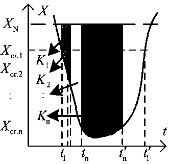
[0020] Step 1. Combined with the voltage stability requirements of the power system for the load bus and the central bus, limit the transient minimum voltage and the steady-state recovery voltage level, and construct a transient voltage stability margin index based on a m...


PUM


Abstract

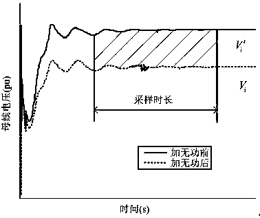
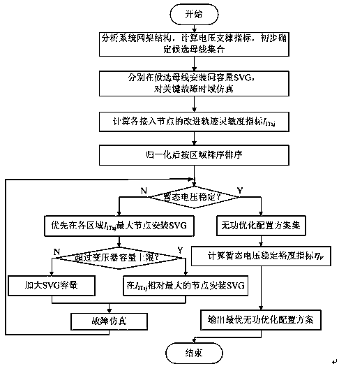
The invention discloses a transient voltage control method. The method can quantitatively evaluate transient voltage stability based on transient voltage stability margin index, and combines improvedvoltage reactive trajectory sensitivity to optimize a reactive configuration scheme of an AC / DC receiving-end power grid. The method comprises the following steps: to begin with, in combination with voltage stability requirements of a power system for a load bus and a pivot bus, limiting transient minimum voltage and steady-state recovery voltage levels, and for the idea of assigning different weights according to different drop degrees, constructing a transient voltage stability margin index based on a multi-binary table; then, proposing a voltage stability support (VSS) index for the condition of a multi-direct-current feed-in receiving-end power grid, and screening a candidate bus for reactive power compensation; then, improving the voltage reactive track sensitivity index by utilizingthe transient voltage stability margin index; and finally, providing an AC / DC receiving-end power grid dynamic reactive power optimization configuration scheme combining the improved voltage reactivepower track sensitivity and the transient voltage stability margin index.

Description

technical field [0001] The invention relates to the technical field of power system operation control, in particular to a transient voltage control method. Background technique [0002] With the implementation of the West-to-East power transmission strategy, my country's power system has entered the era of large power grids, large units, and long-distance power transmission. The scale of distance transmission continues to increase. Through the UHV DC transmission project, the power of the large thermal power base, the large wind / solar new energy base, and the southwest large hydropower base will be fed into the load center centrally, forming a multi-DC feed into the receiving-end power grid. The characteristics of "strong direct and weak alternating current" of the receiving end power grid are prominent, and the problem of transient voltage stability is more serious. HVDC transmission consumes a large amount of reactive power while transmitting active power, which will brin...

Claims


Application Information

Patent Timeline
IPC IPC(8): H02J3/16
CPCH02J3/16Y02E40/30
Inventor 薛安成付潇宇
Owner NORTH CHINA ELECTRIC POWER UNIV (BAODING)
Learn More