Electric line fitting wire cross arm

A power line and cross-arm technology, which is applied in the spatial arrangement/configuration of cables, building types, buildings, etc., can solve the problems of no connection of cross-arms, wire contact interference, poor wind resistance, etc., to improve wind resistance, The effect of improving stability and improving structural stability

Active Publication Date: 2020-02-11
湖南恒力通电气设备科技有限公司
6 Cites 7 Cited by

AI-Extracted Technical Summary

Problems solved by technology

[0003] 1. Since most of the crossarms erected on the same utility pole are crossarms of the same specification, the longitudinal positions of the wires erected up and down are on the same plane. Since the wires on the crossarms are mostly erected outdoors, when the outdoor wind is strong, at the same time When too many ...

Method used

Between described sealing block 143 and mounting hole 142, be threaded connection, sealing block 143 is connected with rotating plate 141 upper end face by connecting rope, and connecting rope surface cover is provided with insulating leather sheath, has improved the intensity of connecting rope At the same time, it plays the role of sleeve protection. When the insulator needs to be connected with the installation hole 142 , the sealing block 143 is unscrewed, so that the insulator is installed on the rotating plate 141 through the installation hole 142 .
Described fixed block 41 rear end is provided with fastening hole, and the inner end of fixed block 41 is provided with arc-shaped groove, and the outside of the middle part of arc-shaped groove is convex structure, and the outer end of replacement block 42 is arc-shaped Structure, the middle part of the outer end of the replacement block 42 is a raised block, the replacement block 42 is snapped into the arc-shaped groove, the fixed block 41 and the replacement block 42 are connected by bolts, and the fixed block 41 and the replacement block 42 are detachably connected. Adjusting the shape of the fixing device 4 according to different types of utility poles improves the fit degree with the utility poles.
Described telescopic installation group 12 comprises positioning block 121, mounting plate 122, positioning member 123, back-moving spring 124 and protective cover 125, and positioning block 121 is connected with the access groove by the mode of sliding fit, and the outer end of positioning block 121 Mounting plate 122 is installed, and cross bar 11 is connected with locating member 123 by the mode of sliding fit, and back-moving spring 124 is connected between locating member 123 and the outer wall of cross bar 11, and back-moving spring 124 plays the effect of connection reset, and back-moving spring 124 The ou...

Abstract

The invention relates to an electric line fitting wire cross arm comprising cross arm assemblies, reinforcing rods, a locating frame and fixing devices. The reinforcing rods are connected between thecross arm assemblies in a clamped manner. The reinforcing rods are in bilateral symmetry. The locating frame is arranged in the middle of the cross arm assemblies. The fixing devices are installed inthe middle of the back ends of the cross arm assemblies. The electric line fitting wire cross arm can solve the problem that since most of the cross arms erected on the same pole are identical in specification, the longitudinal positions of the wires erected on the upper side and the lower side are located on the same plane, considering that most of the electric wires on the cross arms are erectedoutdoors, when outdoor wind is strong and excessive electric wires are erected, the wires erected on the upper side and the lower side are prone to make contact and generate interference, no connection exists between the existing cross arms, the single cross arm is poor in wind resistance when the wind is strong, and the number of insulators installed on each single cross is certain and cannot beincreased.

Application Domain

TowersSpatial arrangements/dispositions of cables

Technology Topic

Image

  • Electric line fitting wire cross arm
  • Electric line fitting wire cross arm
  • Electric line fitting wire cross arm

Examples

  • Experimental program(1)

Example Embodiment

[0035] The embodiments of the present invention will be described below with reference to the drawings. In this process, to ensure the clarity and convenience of the description, we may exaggerate the width of the line or the size of the constituent elements in the illustration.
[0036] In addition, the following terms are defined based on the functions of the present invention, and may be different according to the intentions or conventions of users and operators. Therefore, these terms are defined based on the entire content of this specification.
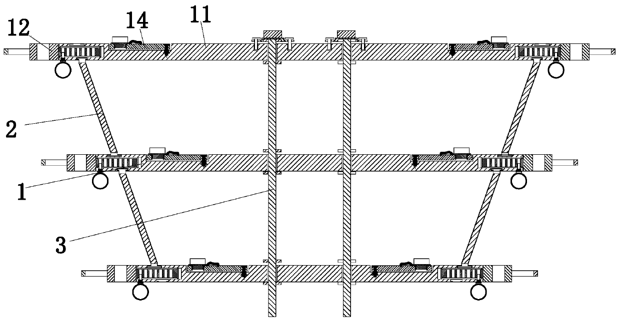
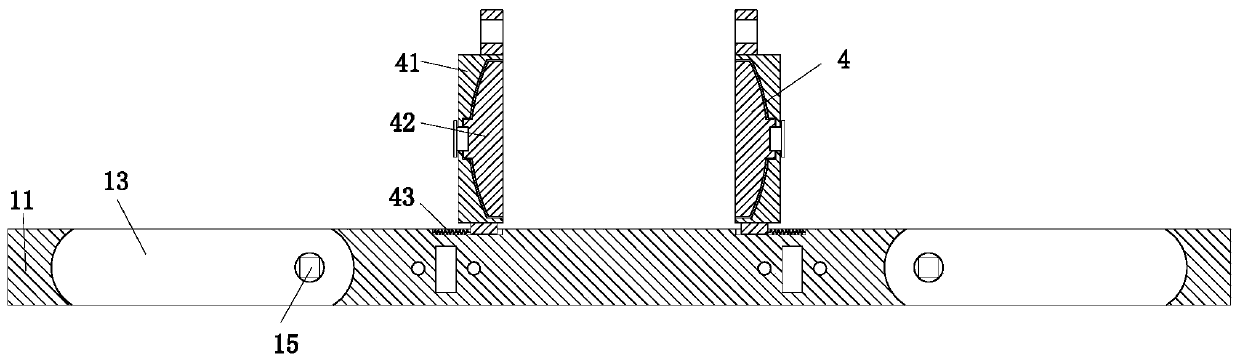
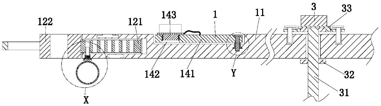
[0037] Such as Figure 1 to Figure 9 As shown, a power line accessory wire cross arm includes a cross arm group 1, a reinforcing rod 2, a positioning frame 3, and a fixing device 4. The cross arm group 1 is clamped with a reinforcing rod 2, and the reinforcing rod 2 It is arranged symmetrically, the middle of the cross arm group 1 is provided with a positioning frame 3, and the middle of the rear end of the cross arm group 1 is equipped with a fixing device 4.
[0038] The cross arm set 1 includes a cross bar 11, two telescopic installation groups 12, two hidden grooves 13, two adjustment mechanisms 14, two connecting grooves 15 and two connecting pieces 16, and the left and right ends of the cross bar 11 There are two telescopic installation groups 12, the left and right ends of the cross bar 11 are provided with two hidden grooves 13, and the two hidden grooves 13 are located between the two telescopic installation groups 12, and the inner ends of the hidden groove 13 are connected with connecting grooves 15. The adjusting mechanism 14 is located in the hidden groove 13, and a connecting piece 16 is provided between the adjusting mechanism 14 and the connecting groove 15. The telescopic installation group 12 and the adjusting mechanism 14 both function as fixing the insulator, and the connecting piece 16 is provided The adjustment mechanism 14 changes to the locking function.
[0039] The left and right ends of the cross bar 11 are provided with inlet and outlet grooves, the lower end of the cross bar 11 is provided with two embedding grooves, and each embedding groove is located below one inlet and outlet groove, and the upper end of the cross bar 11 is provided with two cards Each of the clamping grooves is located above an in and out groove, and the reinforcing rod 2 is embedded between the embedding groove and the clamping groove to support the two horizontal rods 11 arranged up and down, which plays the role of strengthening and fixing. Wind resistance.
[0040] The telescopic installation set 12 includes a positioning block 121, a mounting plate 122, a positioning piece 123, a return spring 124, and a protective sleeve 125. The positioning block 121 is connected to the inlet and outlet grooves by sliding fit, and the outer end of the positioning block 121 is installed with a mounting Plate 122, the cross bar 11 is connected to the positioning member 123 by a sliding fit, a return spring 124 is connected between the positioning member 123 and the outer wall of the cross bar 11, the return spring 124 plays the role of connecting and resetting, and the outer sleeve of the return spring 124 A protective sleeve 125 is provided. The protective sleeve 125 prolongs the corrosion time of the return spring 124. During specific work, install the insulator on the mounting plate 122. When the position of the insulator needs to be adjusted horizontally, pull the positioning member 123 downward and move the mounting plate left and right. After 122, the positioning member 123 is released, so that it is locked in the positioning groove again.
[0041] The surface of the hidden groove 13 is coated with anti-rust paint to prevent corrosion. The left and right ends of the hidden groove 13 are arc-shaped structures, and the upper part of the connecting groove 15 is an inverted T-shaped cylindrical cavity structure. The lower half of the groove 15 is a rectangular cavity structure, the upper half of the connecting groove 15 is connected to the rotating cylinder 145 in rotation, and the connecting member 16 is inserted into the lower half of the connecting groove 15 to angularly position the rotating plate 141
[0042] The adjusting mechanism 14 includes a rotating plate 141, a mounting hole 142, a sealing block 143, a through hole 144, and a rotating cylinder 145. The outer end of the rotating plate 141 is provided with a mounting hole 142, and a sealing block 143 is provided in the mounting hole 142 to seal The block 143 seals the unused mounting hole 142, the inner end of the rotating plate 141 is provided with a through hole 144, the lower end of the through hole 144 is mounted with a rotating cylinder 145, and the upper half of the rotating cylinder 145 and the connecting groove 15 is Embedded connection, there is a movable connection between the rotating plate 141 and the connecting groove 15. During specific work, when the number of insulators needs to be increased in the horizontal position, the connecting piece 16 is drawn out, and the rotating plate 141 is rotated forward by ninety degrees and then the connecting piece is reinserted 16. To reposition the rotating plate 141, install the insulator on the rotating plate 141 through the mounting hole 142.
[0043] The positioning frame 3 includes a connecting column 31, a limiting plate group 32, and a rotating frame 33. The connecting column 31 is uniformly installed with the limiting plate group 32 from top to bottom. The upper end of the connecting column 31 is equipped with a rotating frame 33. , Insert the positioning frame 3 downward from the insertion slot, and the position of the limit plate and the insertion slot need to be aligned for smooth insertion. After inserting, the positioning frame 3 is rotated as a whole, and then the positioning frame 3 is locked by the threaded column. The setting of the cross arm has the function of separating the cross arm group 1 and supporting the effect.
[0044] The fixing device 4 includes two fixing blocks 41, two replacement blocks 42 and two buffer springs 43. The two fixing blocks 41 are connected to the cross bar 11 by a sliding fit, and the front outer wall of the fixing block 41 is passed through the buffer spring. 43 is connected to the crossbar 11, and a replacement block 42 is provided inside the fixed block 41. During specific work, it is fixed and installed according to the shape of the pole. When the pole has a cylindrical structure, the two replacement blocks 42 are taken out and the two The two fixing blocks 41 are fixed on the telephone pole in an embracing manner, and the two fixing blocks 41 are locked and fixed by bolts to position the cross arm group 1 at a high level, which improves the degree of adhesion to the telephone pole.
[0045] The middle part of the cross bar 11 is provided with two insertion groove groups, and the insertion groove group is composed of an insertion groove and two corresponding holes, and the two corresponding holes are located on the left and right sides of the insertion groove. The positioning frame 3 is inserted from the insertion groove. , Rotate 90 degrees, insert the threaded column into the corresponding hole, and then connect with the threaded hole.
[0046] The positioning block 121 is uniformly provided with positioning grooves from left to right, and the upper end of the positioning member 123 is located in the positioning groove, and the lower end of the positioning member 123 is provided with a pull handle to facilitate the personnel to pull down.
[0047] The sealing block 143 is connected with the mounting hole 142 by a screw thread. The sealing block 143 is connected to the upper end surface of the rotating plate 141 by a connecting rope, and the surface of the connecting rope is covered with an insulating holster, which improves the strength of the connecting rope and at the same time. The protective function of the sleeve is that when the insulator needs to be connected to the mounting hole 142, the sealing block 143 is unscrewed, so that the insulator is mounted on the rotating plate 141 through the mounting hole 142.
[0048] The rotating cylinder 145 has an inverted T-shaped structure. The rotating cylinder 145 and the upper half of the connecting groove 15 are embedded and connected. The arrangement of the inverted T-shaped structure allows the rotating cylinder 145 and the upper half of the connecting groove 15 to rotate without separating. , And the inner wall of the rotating cylinder 145 is provided with a rectangular cavity, and the connecting member 16 can pass through the rectangular cavity and be inserted into the lower half of the connecting groove 15 to angularly position the rotating plate 141.
[0049] The upper end of the connecting member 16 is provided with a buckle plate, and the buckle plate is located on the upper inner side of the through hole 144. The lower end of the connecting member 16 is a rectangular column, and the rectangular column passes through the through hole 144, from top to bottom. A rectangular cavity and the lower half of the connecting groove 15.
[0050] The left and right ends of the turret 33 are provided with two through holes, and threaded posts are arranged in the through holes. The lower end of the threaded posts and the corresponding holes are threadedly connected, and the limit plate group 32 is limited by two Bit board composition;
[0051] The rear end of the fixed block 41 is provided with a fastening hole, the inner end of the fixed block 41 is provided with an arc-shaped groove, and the middle outside of the arc-shaped groove is a convex structure, and the outer end of the replacement block 42 is an arc structure. The middle of the outer end of the block 42 is a raised block, the replacement block 42 is clamped into the arc-shaped groove, the fixed block 41 and the replacement block 42 are connected by bolts, and the fixed block 41 and the replacement block 42 are detachably connected according to different types The utility pole adjusts the shape of the fixing device 4 to improve the degree of adhesion with the utility pole.
[0052] The length of the cross bar 11 is gradually shortened from top to bottom, so that the longitudinal positions of the insulators arranged up and down are staggered, which reduces the interference after the wires are connected.
[0053] in working:
[0054] S1. Assembly: Insert the positioning frame 3 downward from the insertion slot, and then rotate the positioning frame 3 as a whole after insertion, lock the positioning frame 3 through the threaded column, and then use the reinforcing rod 2 to embed and strengthen the connection between the cross arm groups 1;
[0055] S2. Installation: transport the present invention to the upper end of the pole, and fix it on the upper end of the pole by the fixing device 4;
[0056] S3. Fixing of the insulator: install the insulator on the mounting plate 122, pull down the positioning piece 123, and determine the position of the mounting plate 122 by moving the mounting plate 122 left and right. After confirming, loosen the positioning piece 123 to make it snap into position again Lock the position of the mounting plate 122 in the slot;
[0057] S4. When it is necessary to increase the number of lateral insulators, pull out the connecting piece 16, rotate the rotating plate 141 forward by ninety degrees, and then re-insert the connecting piece 16 to reposition the rotating plate 141 and pass the added insulator through the mounting hole 142 Installed on the rotating plate 141;
[0058] S5. Wire connection: Connect wires through insulators.
[0059] In addition, it should be understood that although this specification is described in accordance with the implementation manners, not each implementation manner only includes an independent technical solution. This narration in the specification is only for clarity, and those skilled in the art should consider the specification as a whole The technical solutions in the embodiments can also be appropriately combined to form other implementations that can be understood by those skilled in the art.

PUM

no PUM

Description & Claims & Application Information

We can also present the details of the Description, Claims and Application information to help users get a comprehensive understanding of the technical details of the patent, such as background art, summary of invention, brief description of drawings, description of embodiments, and other original content. On the other hand, users can also determine the specific scope of protection of the technology through the list of claims; as well as understand the changes in the life cycle of the technology with the presentation of the patent timeline. Login to view more.

Similar technology patents

Classification and recommendation of technical efficacy words

  • Improve stability
  • Less intrusive

Surgical ligature clip

InactiveUS20080312670A1Improve stabilityAvoid spaceWound clampsOrthodontic ligatureArm moving
Owner:AESCULAP AG

Distributed service tracking method, system, storage medium and electronic equipment

InactiveCN108038145AGuaranteed stability and high availabilityLess intrusiveData switching networksSpecial data processing applicationsService processElectronic equipment
Owner:CTRIP TRAVEL NETWORK TECH SHANGHAI0

Recessed ceiling mounted passive infrared detector

ActiveUS20060237651A1Facilitate typeLess intrusiveRadiation pyrometryMaterial analysis by optical meansCeiling mountEngineering
Owner:ADEMCO INC

High-purity aluminium single-layer crystal solidification purifying method

InactiveCN1438339ALess intrusiveImprove removal efficiencyLiquid interfaceAnalysis method
Owner:SHANGHAI JIAO TONG UNIV

Scanner and coaxial and non-coaxial radar systems using same

ActiveCN111856481ALess intrusiveRealize 3D ImagingElectromagnetic wave reradiationOptical switchOptical amplifier
Owner:HANGZHOU XIGHT SEMICON CO LTD
Why Eureka
Try Eureka