
System and method for seismological sounding

a seismological and sounding technology, applied in the field of seismological sounding systems and methods, can solve the problems of large equipment that is not convenient to transport to a sounding location without specialized vehicles, large equipment that is not convenient to transport, and large energy inputs, etc., to achieve the effect of increasing the signal-to-noise ratio (snr), reducing the number of noise, and less cumbersome transportation

Inactive Publication Date: 2011-03-24
ERICKSON ALAN
View PDF17 Cites 23 Cited by
  • Summary
  • Abstract
  • Description
  • Claims
  • Application Information

AI Technical Summary

Benefits of technology

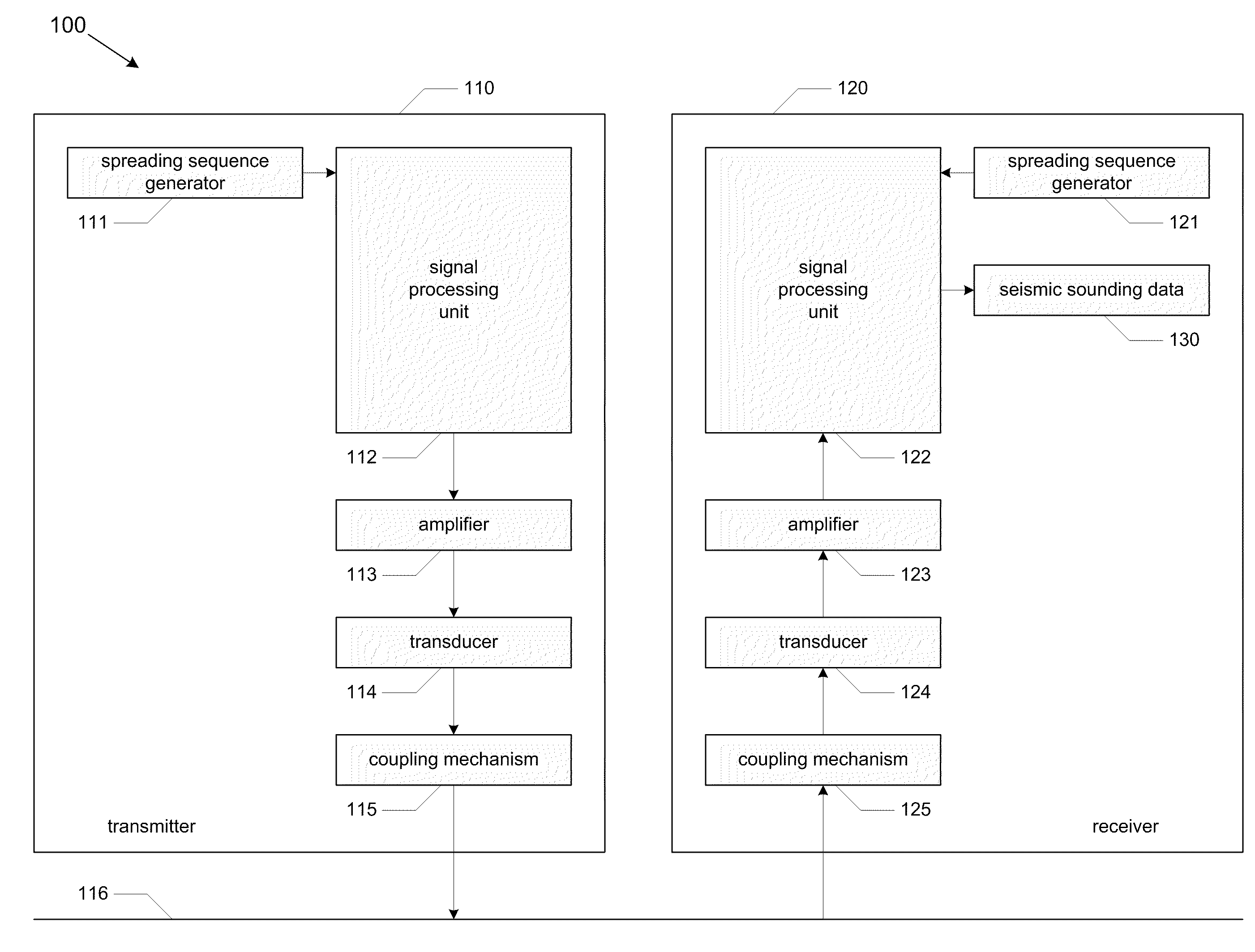
"The present invention provides a system and method for seismological sounding by generating a continuous spread spectrum signal and transmitting it to a medium through a transmit transducer. The receive transducer receives one or more return signals from the medium, which are processed to obtain seismic sounding data describing the medium. The invention has several technical effects, including the use of lower energy densities, reduced interference from ambient seismic noise, and the ability to control signal parameters. It also allows for the transmission of a smaller amount of energy per unit of time, which can be useful in protected spaces or areas where soundings need to be performed continuously but must remain unobtrusive. The invention can be used in both scientific research and commercial applications."

Problems solved by technology

The standard practice has a number of inherent challenges and drawbacks.
First, impulse stimulation sources require large energy inputs in order to overcome signal attenuation within the earth.
Generating the necessary large energy pulses can be expensive and invasive, requiring large equipment that is not convenient to transport to a sounding location without specialized vehicles.
This limitation can make sounding with impulse stimulation sources particularly difficult in remote or difficult to access locations.
Second, the detected impulse signals are not easily distinguishable from sources of interference, such as amplifier noise, road traffic, mining, or natural seismic events.
This limits the ability to perform accurate soundings in areas of high ambient seismic noise.
Third, most impulse sources contain consumable elements (e.g., explosives) and are therefore not suitable for permanent or semi-permanent emplacement (e.g. to continuously monitor for tunneling activity across a border or into a secure site).
As a result, they suffer significantly from the attenuation and interference effects described above,
Fourth, impulse sources provide very little control over the parameters of the emitted signal, such as spectral distribution.
Using impulse based signal sources, such selectivity is generally unavailable.
Fifth, sounding methods using impulse sources are easy for third parties to detect and thus are relatively ineffective for surreptitious applications.
For example, impulse sources would be inadequate to monitor for tunnel construction across a border or into a secure area without notifying the builders or users of the tunnel to the monitoring.
Relatedly, because of their sensitivity to interference, impulse based soundings may be subject to jamming efforts (e.g., tunnel users may thwart detection of the tunnel by creating additional seismic noise in the area).
Sixth, in many circumstances, impulse sources are too intrusive or destructive.
For example, impulse sources may be a nuisance or hazard in heavily populated or crowded areas, urban environments, wildlife refuges, cave systems and other protected spaces, potentially fragile environments such as unstable mineshafts, etc.
Furthermore, impulse sources are typically too obtrusive to be run continuously for monitoring secure locations such as power plants, military sites, bank vaults, etc.
Seventh, it is generally not possible to distinguish between separate impulses.
Thus, multiple simultaneous impulses appear as interference.

Method used


Image

  • System and method for seismological sounding
  • System and method for seismological sounding
  • System and method for seismological sounding

Examples


example

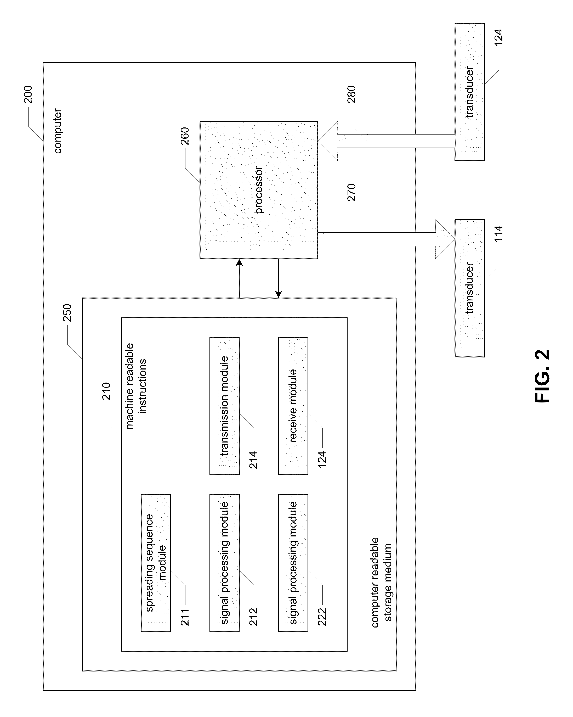
[0074]An embodiment of the above described seismic sounding systems and methods was used to perform a seismic survey at the South Juanita Mine adit in the Magdalena Mountains. The embodiment used to perform the seismic survey described comprised an AudiSource Amp5.3 amplifier coupled to a Clark Synthesis TST429 Platinum transducer, GeoSpace GS-100 geophones, an IOTech Personal DAQ 3001, and a Dell Latitude D620 laptop computer. The transmitter is a commercially available amplifier and a low-power audio transducer, and the receiver is a commercial single-axis geophone. The transmitter and laptop were powered by a Black and Decker PI750AB power inverter plugged into the field vehicle. The transmitter was coupled to the ground via a small steel stake hand driven with a hammer, and the single geophone was moved to measured offsets.

[0075]The following computer code, which is written in C++, can be used to control I / O and to perform signal processing, as described above, with regard to pe...


PUM


Abstract

Systems and methods for seismological sounding with acoustic signals and, more particularly, systems and methods for performing geophysical surveys using spread spectrum acoustic waves generated by non-impulsive sources. A spread spectrum signal is generated and coupled to a medium that is to be sounded for propagation of an acoustic wave through the medium. One or more return signals are received from the medium that are generated by interaction between the acoustic wave and the medium. The return signals are possessed to obtain seismic sounding data describing the structural features of the medium.

Description

BACKGROUND OF THE INVENTION[0001]1. Field of the Invention[0002]The present invention relates to systems and methods for seismological sounding with acoustic signals. More particularly, aspects of the present invention relate to systems and methods for performing geophysical surveys using spread spectrum acoustic waves generated by non-impulsive sources.[0003]2. Description of the Background[0004]The conventional practice of reflection seismology makes use of an energy impulse to inject acoustic waves into the earth. Common methods of creating this impulse include explosions, air guns, dropped weights, and vibrating plates. The seismic waves resulting from these impulse sources then propagate through the earth, undergoing reflection and refraction due to discontinuities or gradations in density in the earth. Such discontinuities delineate boundaries between features such as water tables, rock layers, caves, faults, or man-made structures such as tunnels. A signal composed of the sum...

Claims


Application Information

Patent Timeline
Patent Type & Authority Applications(United States)
IPC IPC(8): H04B1/00G01V1/28H04B1/707
CPCG01V1/28G01V1/005
Inventor ERICKSON, ALAN
Owner ERICKSON ALAN
Learn More