
Calibration method for machine vision and positioning and grabbing method for mechanical arm

A technology of machine vision and calibration method, which is applied in the field of calibration, can solve the problems of low efficiency, achieve high calibration efficiency, and improve the effect of grasping efficiency

Active Publication Date: 2020-02-14
SHANGHAI ORIGINCELL BIOLOGICAL CRYO EQUIP CO LTD
View PDF6 Cites 1 Cited by
  • Summary
  • Abstract
  • Description
  • Claims
  • Application Information

AI Technical Summary

Problems solved by technology

At present, the mainstream calibration method of machine vision is to obtain the projection relationship between world coordinates and image coordinates through a series of data collection, and manually confirm the coordinate values ​​of key points. Therefore, the calibration efficiency is low

Method used


Image

  • Calibration method for machine vision and positioning and grabbing method for mechanical arm

Examples


Embodiment Construction

[0045] The specific implementation manners of the present invention will be further described in detail below in conjunction with the accompanying drawings and embodiments. The following examples are used to illustrate the present invention, but are not intended to limit the scope of the present invention.

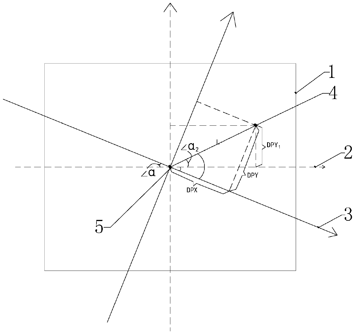
[0046] see figure 1 , a kind of calibration method of machine vision of a preferred embodiment of the present invention, comprises the following steps:

[0047] S1. The robotic arm grabs the calibration object and places it in the calibration area, and records the world coordinates (RWX) of the robotic arm when the calibration object is placed in the calibration area. 1 , RWY 1 );

[0048]The calibration area is artificially set. In this calibration area, the robotic arm can pick up and place the calibration object through the grasping device on it, that is, the manipulator, and the machine vision on the robotic arm can take pictures of the calibration object. Machine ...


PUM


Abstract

The invention relates to a calibration method for machine vision. The projection relation between world coordinates and image coordinates can be directly calculated through a series of data, the relative position relation between a CCD and a mechanical arm is calibrated and calculated, and therefore the relative displacement parameter needing to be adjusted by the mechanical arm can be directly calculated through the image coordinates of a target object, and then positioning and grabbing of machine vision are achieved without manually calibrating the coordinate value of a key point. Therefore,compared with a traditional calibration method, the calibration method for machine vision is high in calibration efficiency. In addition, the invention further designs a positioning and grabbing method for the mechanical arm. According to the positioning and grabbing method for the mechanical arm, the target object can be automatically positioned and grabbed through the calibration result of thecalibration method for machine vision.

Description

technical field [0001] The present invention relates to a calibration method, in particular to a machine vision calibration method. In addition, the present invention also designs a robotic arm positioning and grasping method based on the machine vision calibration method. Background technique [0002] The robotic arm is a device that automatically locates and grabs products through the machine vision recognition system. The machine vision recognition system needs to be calibrated before positioning the product to realize the conversion between the world coordinate system and the image coordinate system and The confirmation of the coordinates of the key points enables accurate identification and positioning of the product. Therefore, it is one of the keys for the robotic arm to accurately grasp the product. At present, the mainstream calibration method of machine vision is to obtain the projection relationship between world coordinates and image coordinates through a series ...

Claims


Application Information

Patent Timeline
IPC IPC(8): B25J9/16B25J19/00
CPCB25J9/1692B25J19/0095
Inventor 瞿建国周叶林毛晓峰王建信
Owner SHANGHAI ORIGINCELL BIOLOGICAL CRYO EQUIP CO LTD
Learn More