Connector of light-emitting diode(LED) lamp strip

A technology of LED light strips and connectors, which is applied to the semiconductor devices of light-emitting elements, components of lighting devices, lighting devices, etc. Prevent loosening and facilitate plug-in and fixation

Inactive Publication Date: 2020-02-14
崇义县佰盛五金制品有限公司
View PDF6 Cites 0 Cited by
  • Summary
  • Abstract
  • Description
  • Claims
  • Application Information

AI Technical Summary

Problems solved by technology

At present, the following needs to be used when connecting the light strip figure 1 The light strip connection pole 5 shown realizes the connection with the ballast. The existing light strip connection pole 5 consists of several pins 51 and connectors 52 connecting the pins 51. The light strip connection pole 5 During the installation, it is necessary to manually plug the pin 51 to the light strip, which is more laborious; and in the long-term use process, the pin 51 and the light strip will become loose, and it is easy to have poor contact, resulting in the light strip not working

Method used


Image

  • Connector of light-emitting diode(LED) lamp strip
  • Connector of light-emitting diode(LED) lamp strip
  • Connector of light-emitting diode(LED) lamp strip

Examples


Embodiment

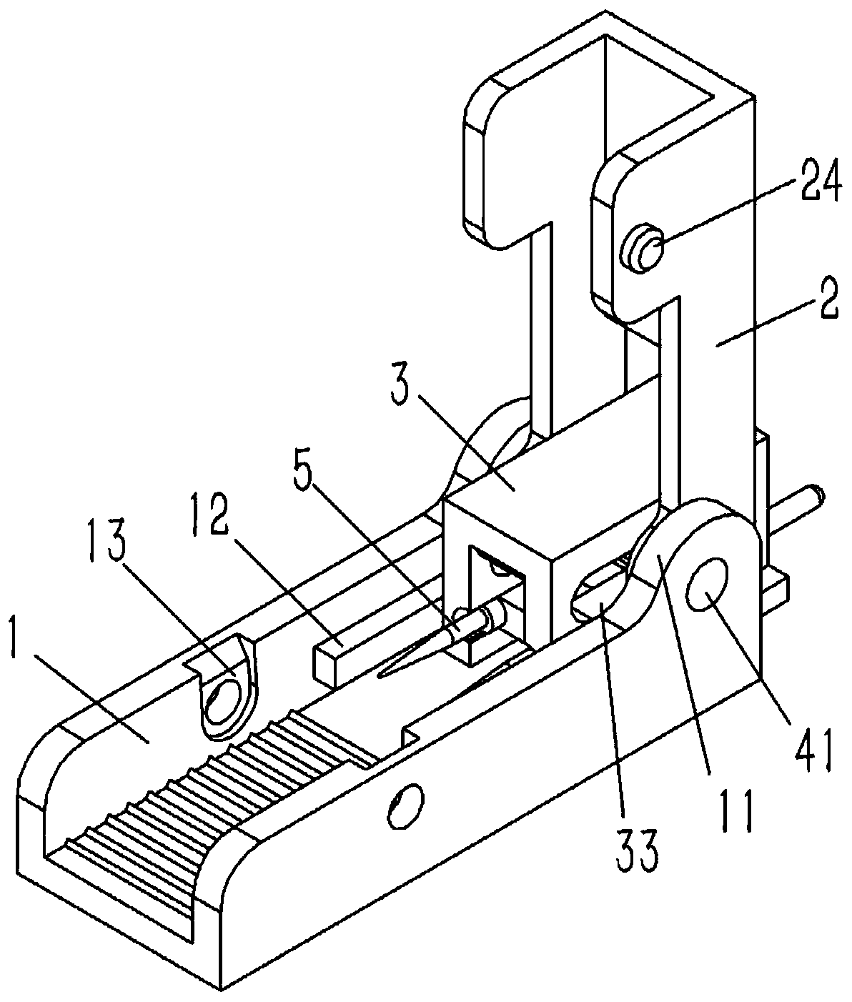
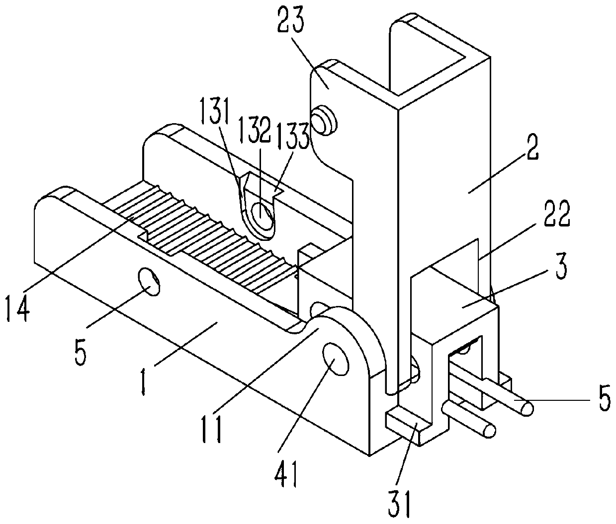
[0021] Example: see Figures 2 to 5 As shown in the figure, a connector for an LED light strip includes a "凵"-shaped slot seat 1 and a "冂"-shaped slot cover 2, the slot cover 2 is inserted in the slot seat 1, and the front end side wall of the slot cover 2 An upper lug 21 is formed, a semicircular lower lug 11 is formed on the side wall of the front end of the groove seat 1, and a horizontal bar 12 is formed on the inner side wall of the groove seat 1 below the lower lug 11; The groove seat 1 is inserted with a sliding seat 3 in the shape of "冂", the two sides of the lower end of the sliding seat 3 are formed with guide strips 31, and the guide strips 31 are inserted between the retaining strip 12 and the inner bottom surface of the groove seat 1; A rack 32 is formed on the bottom surface of the inner side of the sliding seat 3, and a horizontal guide groove 33 is formed on the side wall of the sliding seat 3 on the lower side of the rack 32. The gear shaft 4 is engaged with t...


PUM


Abstract

The invention discloses a connector of a light-emitting diode(LED) lamp strip. The connector comprises a right-angled-U-shaped groove seat and an inverted-U-shaped groove cover, wherein the groove cover is inserted into the groove seat, upper support lugs are formed on the side walls of the front end of the groove cover, semicircular lower support lugs are formed on the side walls of the front endof the groove seat, and horizontal stop bars are formed at the positions, on the lower sides of the lower support lugs, of the inner side walls of the groove seat; an inverted-U-shaped sliding seat is inserted into the groove seat, guide bars are formed on the two sides of the lower end of the sliding seat, and the guide bars are inserted between the stop bars and the bottom surface of the innerside of the groove seat; and a rack is formed on the bottom surface of the inner side of the sliding seat, horizontal guide grooves are formed in the position, on the lower side of the rack, of the side wall of the sliding seat, a gear shaft is engaged on the rack, two ends of the gear shaft penetrate through the guide grooves of the sliding seat and are fixedly connected to the upper support lugsof the groove cover in an inserted mode, support shafts are formed at two ends of the gear shaft, and the support shafts penetrate through the upper support lugs and are arranged on the lower supportlugs of the groove seat in an inserted mode. According to the connector, connecting poles on the lamp strip can be conveniently inserted and fixed, the connecting poles can be prevented from loosening, and the poor contact condition can be avoided.

Description

technical field [0001] The present invention relates to the technical field of electrical connectors, in particular to a connector for LED light strips. Background technique [0002] The light strip refers to welding the LED light on the copper wire or the strip-shaped flexible circuit board with a special processing technology, and then connecting it to the power supply to emit light. It is named for its shape like a light strip when it emits light. Light strips have been widely used in buildings, bridges, roads, gardens, courtyards, floors, ceilings, furniture, cars, ponds, underwater, advertising, signboards, signs and other fields for decoration or lighting. At present, when connecting the light strip, you need to use the following figure 1 The light strip connection pole 5 shown realizes the connection with the ballast. The existing light strip connection pole 5 consists of several pins 51 and connectors 52 connecting the pins 51. The light strip connection pole 5 Dur...

Claims


Application Information

Patent Timeline
Patent Type & Authority Applications(China)
IPC IPC(8): F21V23/06F21V21/002F21Y115/10
CPCF21V21/002F21V23/06F21Y2115/10
Inventor 秦小燕
Owner 崇义县佰盛五金制品有限公司
Why Eureka
Try Eureka