Quick phase-splitting switcher for alternating-current loop

An AC circuit and switcher technology, used in instruments, electrical measuring instrument parts, measuring devices, etc., can solve the problems of slow construction and acceptance of AC circuits, dangerous, complicated wiring, etc., to simplify access to AC circuits and AC circuits. The process of loop detection test, the effect of simplifying the detection test process and reducing the work intensity of workers

Pending Publication Date: 2020-02-14
STATE GRID TIANJIN ELECTRIC POWER +1
View PDF0 Cites 2 Cited by
  • Summary
  • Abstract
  • Description
  • Claims
  • Application Information

AI Technical Summary

Problems solved by technology

[0002] The secondary AC circuit is divided into four phases A, B, C, and N, while measurement and experimental tools (battery packs, multimeters, direct resistance meters, pointer meters, etc.) often only have two phases + and -, because the interfaces do not correspond, substation construction In the process of inspection and acceptance, frequent manual line changes and line changes are the normal state of work; the AC circuit needs to be connected with protection devices, backup power supplies, fault filter devices, measurement and control devices, and watt-hour meters, so the wiring is complicated and the workload is huge
[0003] Therefore, the construction and acceptance of the AC circuit in the existing technology is slow, complicated, cumbersome, and dangerous. It is necessary to design a tool to improve the commutation efficiency and realize the interface correspondence

Method used


Image

  • Quick phase-splitting switcher for alternating-current loop
  • Quick phase-splitting switcher for alternating-current loop
  • Quick phase-splitting switcher for alternating-current loop

Examples


Embodiment Construction

[0038] In order to make the purpose, technical solutions and advantages of the embodiments of the present invention clearer, the technical solutions of the present invention will be clearly and completely described below in conjunction with the accompanying drawings. Obviously, the described embodiments are part of the embodiments of the present invention, not all of them. the embodiment. Based on the embodiments of the present invention, all other embodiments obtained by persons of ordinary skill in the art without making creative efforts belong to the protection scope of the present invention.

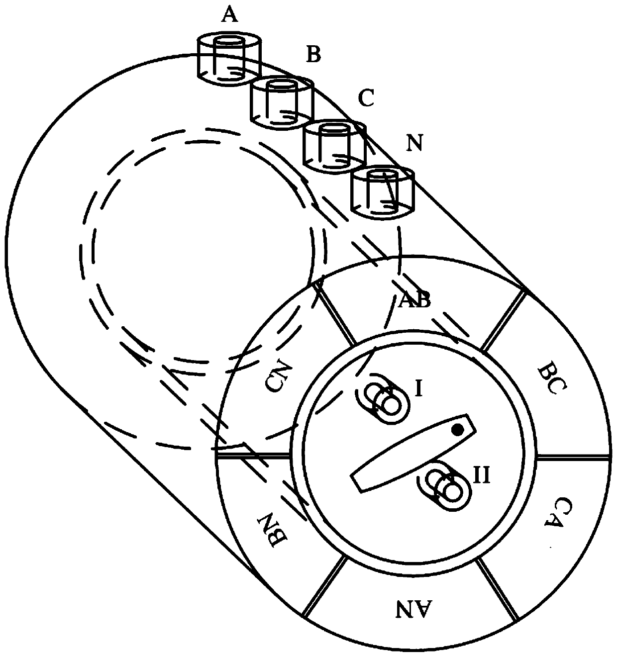
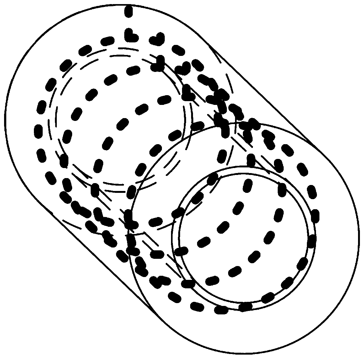
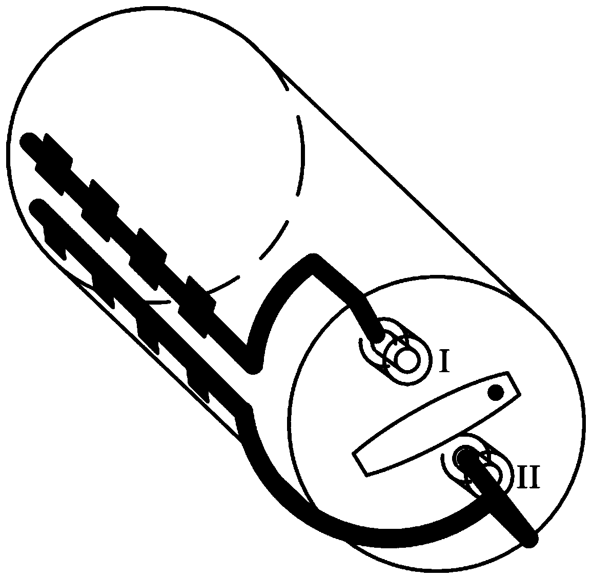
[0039] At present, the wiring of the AC circuit is complicated, and the phase-by-phase measurement process is cumbersome and error-prone. Based on this, a fast phase-splitting switcher for the AC circuit provided by the embodiment of the present invention can solve the problem that the four-phase AC circuit does not correspond to the interface of the two-phase detection instrument. p...


PUM


Abstract

The invention provides a quick phase-splitting switcher for an alternating-current loop and relates to the technical field of AC commutation. The switcher comprises a housing, input binding posts, anoutput binding post, a rotating knob, a rotating shaft, a moving contact, and a static contact. The housing is cylindrical, and the rotary knob is connected with the housing. The rotating shaft is provided with a moving contact, and the rotating knob is connected with the rotating shaft and the moving contact is driven to do axial movement around a central axis of the housing. The input binding posts comprise an A-phase binding post, a B-phase binding post, a C-phase binding post and an N-phase binding post and are arranged on a cylindrical side surface of the housing, and the output binding post is arranged on a bottom surface of the housing and is connected with the rotary knob. The connection of different static contacts is achieved by rotating the rotating knob, and therefore, the phase switching is achieved. Through the phase-splitting switcher provided by the invention, the problem that interfaces of a four-phase alternating-current loop and a two-phase detection instrument do not correspond to each other can be solved, the operation intensity of workers is reduced, and the processes of the connection of a measurement instrument into the alternating-current loop and an alternating-current loop detection test are simplified.

Description

technical field [0001] The invention relates to the technical field of AC commutation, in particular to a fast phase-splitting switcher for an AC loop. Background technique [0002] The secondary AC circuit is divided into four phases A, B, C, and N, while measurement and experimental tools (battery packs, multimeters, direct resistance meters, pointer meters, etc.) often only have two phases + and -, because the interfaces do not correspond, substation construction During the inspection and acceptance process, frequent manual line changes and line changes are the norm; the AC circuit needs to be connected with protection devices, backup power supplies, fault filter devices, measurement and control devices, and watt-hour meters, so the wiring is complicated and the workload is huge. The above status quo makes the construction and acceptance of slow, complex, cumbersome and dangerous AC circuits a difficult task. Therefore, it is necessary to develop a fast phase selection d...

Claims


Application Information

Patent Timeline
Patent Type & Authority Applications(China)
IPC IPC(8): G01R1/04
CPCG01R1/0416
Inventor 甄国栋殷学功谢丹张昌钦张清华兰岚曾禹棠金岩孙沛川王朝阳王琛弘宋平郭林轩宋朝霞王继隆
Owner STATE GRID TIANJIN ELECTRIC POWER
Why Eureka
Try Eureka