

Method used for gas drilling drillstem test
A technology for gas drilling and ground testing, used in surveying, earth-moving drilling, wellbore/well components, etc., can solve the problem of inconvenient installation and fixation of flowmeters, low safety and operability, and prolonged non-drilling time and other problems, to achieve the effect of saving non-drilling time, high safety and reducing drilling costs
- Summary
- Abstract
- Description
- Claims
- Application Information
AI Technical Summary
Problems solved by technology
Method used
Image

Examples
Embodiment 1
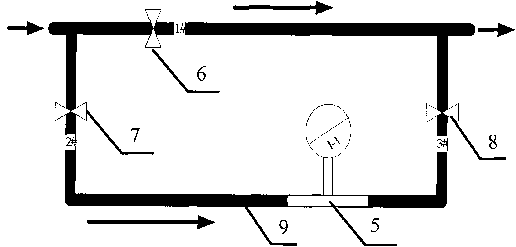
[0026] Refer to the attached figure 1 with 2 , the invention discloses a method for midway testing of gas drilling: firstly, the inner blowout prevention pipeline 1, the choke manifold 2, the ground testing device 3 and the outer blowout pipeline 4 are sequentially connected; The test device 3 includes a manifold 9 connected in series with the gas drilling external discharge pipeline 4, a first flat valve 6, a second flat valve 7, a third flat valve 8 and a measuring unit 5, wherein the first flat The valve 6 is installed on the gas drilling external discharge pipeline 4, the second flat valve 7 and the third flat valve 8 are installed on the manifold 9, the measuring unit 5 is installed on the manifold 9, and the measuring unit Be located between the second flat valve 7 and the third flat valve 8; Secondly, when carrying out the midway test, first open the third flat valve 8, then open the second flat valve 7, and finally close the first flat valve 6, at this time the gas T...
Embodiment 2
[0028] Refer to the attached figure 1 , 2 and 3, as a preferred embodiment of the present invention, the present invention discloses a method for midway testing of gas drilling: first, the internal blowout prevention pipeline 1, the choke manifold 2, the ground testing device 3 and the external blowout The pipelines 4 are connected in sequence; wherein, the ground testing device 3 used includes a manifold 9 connected in series with the gas drilling external discharge pipeline 4, and a first flat valve 6, a second flat valve 7, a third flat valve 8 and The measuring unit 5, wherein the first flat valve 6 is installed on the gas drilling external discharge pipeline 4, the second flat valve 7 and the third flat valve 8 are installed on the manifold 9, and the measuring unit 5 is installed on the On the manifold 9, and the measuring unit is located between the second flat valve 7 and the third flat valve 8; secondly, when carrying out the midway test, first open the third flat va...
Embodiment 3
[0030] A specific example of the present invention is as follows:
[0031] The novel process method of the present invention is realized by a new supporting test device and a control process, and the whole ground test device 3 is a skid-mounted body composed of a manifold 9, a flat valve and a measuring unit 5 (such as figure 2 As shown), it is connected with the gas drilling external blowout pipeline 4.
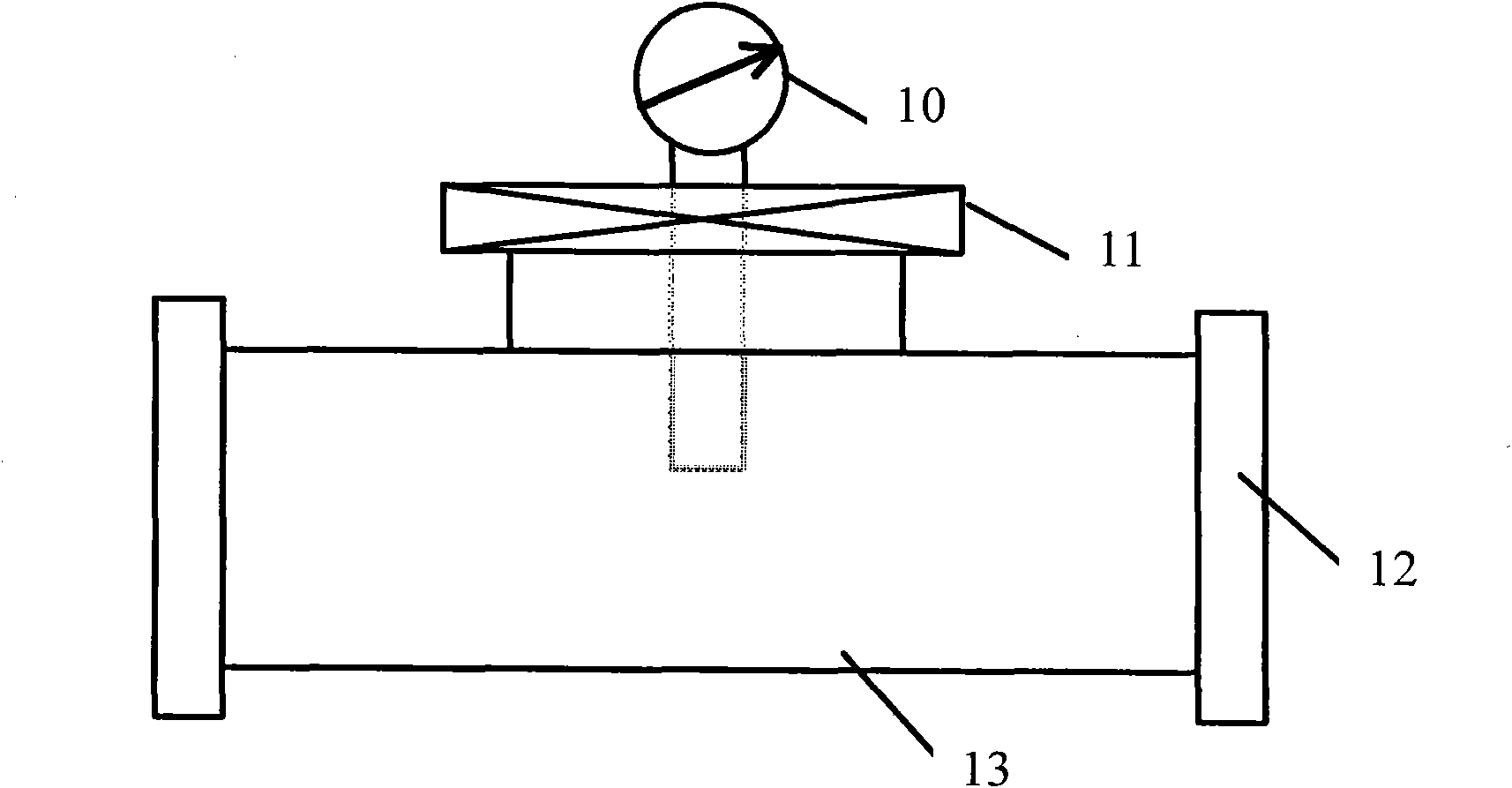
[0032] The measuring unit 5 is the core part of the entire supporting device, and is mainly used to accurately measure the production capacity data (including the flow rate, pressure and temperature of the produced gas).
[0033] The use method of the supporting device involved in the new method is: when the midway test is not carried out, the second flat valve 7 and the third flat valve 8 are normally closed, and the first flat valve 6 is normally open; for the operation method of the midway test, first open the third flat valve Plate valve 8, then open the second plate v...
PUM
 Abstract
Description
Claims
Application Information