
Power grid reactive power resource configuration method based on avoiding voltage out-of-limit

A technology for voltage over-limit and resource allocation, applied in reactive power compensation, AC network voltage adjustment, etc.

Inactive Publication Date: 2020-02-14
STATE GRID ZHEJIANG ELECTRIC POWER
View PDF3 Cites 0 Cited by
  • Summary
  • Abstract
  • Description
  • Claims
  • Application Information

AI Technical Summary

Problems solved by technology

[0005] The technical problem to be solved by the present invention is to overcome the defect that the existing power grid is prone to high and low voltages under the new situation, and to provide a grid reactive resource allocation method that avoids voltage exceeding the limit. Principles, given the applicable reactive power allocation method

Method used


Image

  • Power grid reactive power resource configuration method based on avoiding voltage out-of-limit
  • Power grid reactive power resource configuration method based on avoiding voltage out-of-limit
  • Power grid reactive power resource configuration method based on avoiding voltage out-of-limit

Examples


Embodiment Construction

[0032] In order to describe the present invention more specifically, the technical solutions of the present invention will be described in detail below in conjunction with the accompanying drawings and specific embodiments.

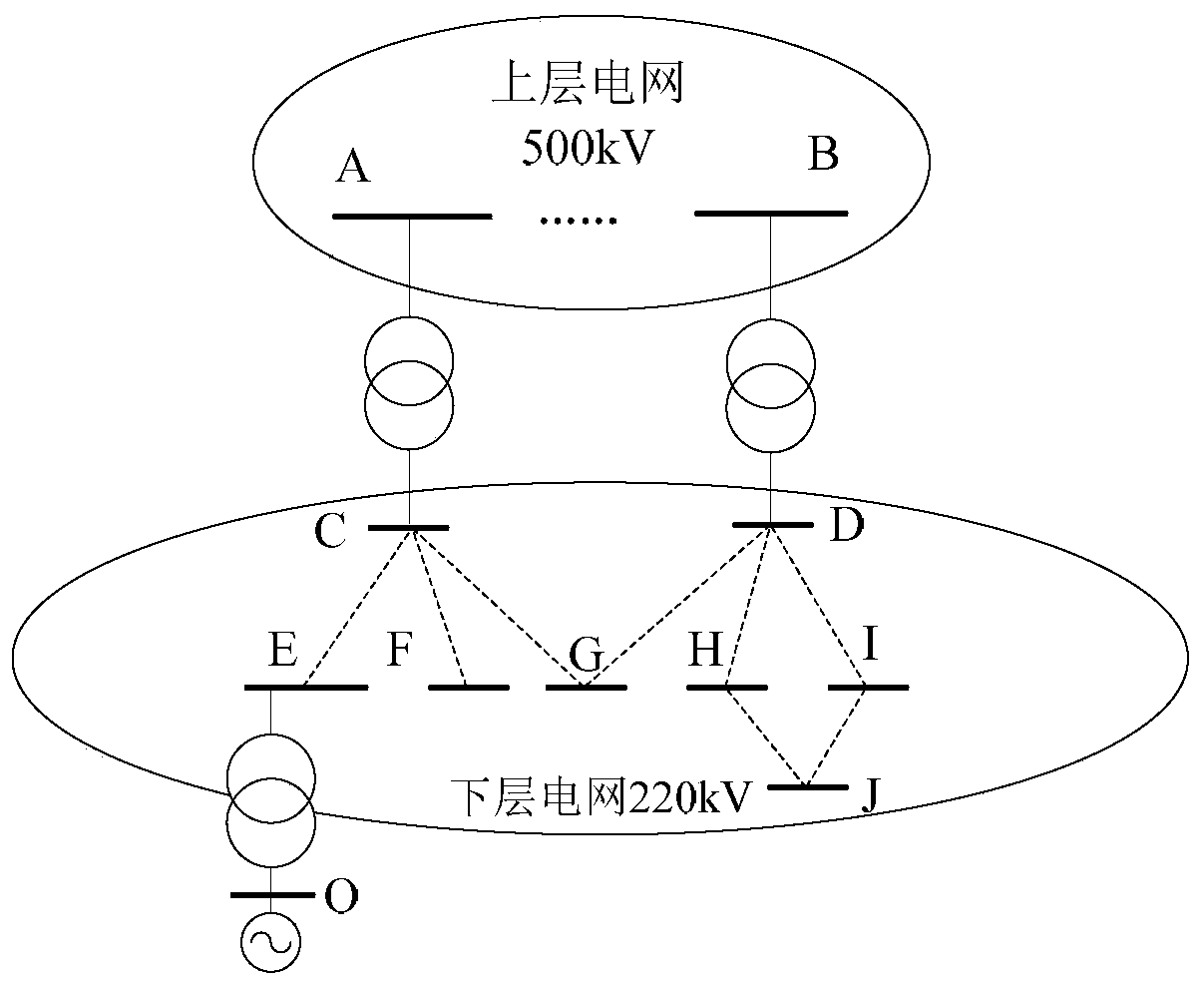
[0033] Such as figure 1 As shown, a schematic diagram of a standard structure of a 500kV power grid is shown, in which points A and B are the high-voltage buses of the 500kV substation, points C and D are the 220kV buses of the 500kV substation, and points E, F, G, and H are , I, J points are the high-voltage bus bars of the 220kV substation.

[0034] For the above-mentioned power grid system, the method for configuring reactive power resources of the power grid according to the present invention is adopted, and the specific process is as follows:

[0035] Step 1: Calculate the reactive power load of the high-voltage busbars in the middle and lower power grids of the area power grid.

[0036] According to the relevant provisions of the "Technical Guidel...


PUM


Abstract

The invention belongs to the technical field of power system control, solves a problem of high and low voltages of local regions caused by internal and external condition changes of a power grid in the prior art and provides a power grid reactive power resource configuration method based on avoiding voltage out-of-limit. The method comprises steps of 1, calculating reactive load of a lower-layer power grid high-voltage bus in a district power grid; 2, setting a voltage allowable range of the lower-layer power grid high-voltage bus in the district power grid; 3, calculating a voltage out-of-limit value of the lower-layer power grid high-voltage bus in the district power grid; 4, judging whether a chip has a voltage out-of-limit condition or not; if not, entering a step 7; if so, sorting thelower-layer power grid high-voltage buses with the voltage out-of-limit according to the out-of-limit value in sequence from large to small; 5, calculating the capacity QN of a reactive power compensation device with the maximum out-of-limit value; 6, returning to the step 3 according to calculation configuration; and 7, configuring reactive compensation capacity Q '0 for the low-voltage side busaccording to requirements of the power factor of the high-voltage bus of the upper-layer power grid.

Description

technical field [0001] The invention belongs to the technical field of electric power system control, and more specifically relates to a method for configuring reactive power resources of a power grid based on avoiding voltage exceeding the limit. Background technique [0002] The operating voltage level of a power system depends on the balance of reactive power in the system. Reasonable reactive resource allocation methods play a vital role in balancing system reactive power, adjusting system operating voltage levels, and ensuring system voltage quality. [0003] At present, the reactive resource allocation of the power grid is mainly carried out in accordance with relevant regulations and specifications. With the development of the new situation of the power grid, the internal and external conditions of the power grid have undergone major changes. The external conditions mainly refer to the fact that after multiple AC and DC UHVs are dropped, the proportion of power recei...

Claims


Application Information

Patent Timeline
Patent Type & Authority Applications(China)
IPC IPC(8): H02J3/16
CPCH02J3/16Y02E40/30
Inventor 何英静李继红郑伟民
Owner STATE GRID ZHEJIANG ELECTRIC POWER
Learn More