Auxiliary base for telegraph pole installation

A utility pole and installation technology, applied in the field of auxiliary bases for utility pole installation, can solve problems such as ground damage, safety accidents, hidden dangers in the normal use of utility poles, etc., and achieve the effect of enhancing stability

Active Publication Date: 2020-02-18
安徽省徽源电杆有限公司
View PDF2 Cites 4 Cited by
  • Summary
  • Abstract
  • Description
  • Claims
  • Application Information

AI Technical Summary

Problems solved by technology

[0002] There are still some deficiencies in the installation of the existing utility poles, which bring potential safety hazards to the normal use of the utility poles; It is easy to loose the connection during the vibration, which will lead to breakage and cause certain safety accidents; in addition, because the base of the utility pole generally has only one fixed device, it is prone to collapse when it is used for a long time or encounters a large external pressure, which not only causes greater harm, and at the same time cause certain damage to the ground, so an auxiliary base for installation of utility poles is designed here to solve the above problems

Method used


Image

  • Auxiliary base for telegraph pole installation
  • Auxiliary base for telegraph pole installation
  • Auxiliary base for telegraph pole installation

Examples


Embodiment 1

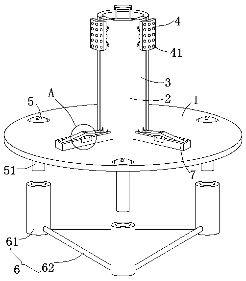
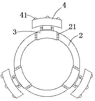
[0026] see Figure 1-5 , this embodiment provides an auxiliary base for installation of utility poles, including a base 1 and a positioning sleeve 2, the positioning sleeve 2 is welded vertically at the center of the top end surface of the base 1, and the axial side of the positioning sleeve 2 The wall is provided with three positioning notches 21 evenly spaced apart, and the inner cavity of each positioning notch 21 is rotated by a pin shaft to be provided with a hinge plate 3 that can rotate between the middle positions of the left and right side walls of the inner cavity of each positioning notch 21, The top of the side wall of each hinge plate 3 away from the center of the inner cavity of the positioning sleeve 2 is hinged with a fitting plate 4 that can swing up and down around the hinge point, and the swing range is between 0 and 30 degrees, and the positioning sleeve 2 The bottom of the outer wall of the outer wall is radially provided with positioning plates 7 facing t...

Embodiment 2

[0032] see Figure 1-5 , further improvements have been made on the basis of Example 1:

[0033] The side wall of each bonding plate 4 away from the hinge plate 3 has several convex points 41 distributed uniformly in a rectangular shape, and the bonding resistance to the side wall of the utility pole cavity is enhanced by setting the convex points 41 .

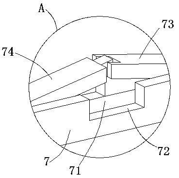
[0034] Every first articulated rod 74 is equal to the height of every second articulated rod 73, and is 1 / 3rd of the inner chamber vertical height of each placement breach 71, by connecting each first articulated rod 74 with each The height of the second articulated rod 73 is equal, and is one-third of the vertical height of the inner cavity of each notch 71, so that after the utility pole is pressed together with the first articulated rod 74 and the second articulated rod 73, it can still be locked. Closed in the inner cavity of the rectangular clamping gap 72, the phenomenon of displacement of the bottom end of the utility po...


PUM


Abstract

The invention discloses an auxiliary base for telegraph pole installation. The auxiliary base for telegraph pole installation comprises a base body and a positioning sleeve, the positioning sleeve isvertically welded to the center position of the top end surface of the base body, three positioning notches which are uniformly distributed at intervals are formed in the axial side wall of the positioning sleeve, an inner cavity of each positioning notch is rotationally provided with a hinge plate which can rotate around the position between the middle section positions of the left side wall andthe right side wall of the inner cavity of the corresponding positioning notch through a pin, the bottom of the outer wall of the positioning sleeve is radially provided with positioning plates rightopposite to the inner cavities of the three positioning notches correspondingly, the top end surfaces of the three positioning plates are provided with placing notches communicating with the inner cavities of the three positioning notches, and the middle section positions of the top ends of the three positioning plates are provided with rectangular clamping notches which communicate with the innercavities of the placing notches and are used for being connected with the side wall of the bottom end of a telegraph pole in a clamped mode. According to the auxiliary base for telegraph pole installation, the safety accident of toppling is not prone to occurrence during installation of the telegraph pole, and the phenomenon of lateral inclination or fracture after the telegraph pole is vibratedis avoided.

Description

technical field [0001] The invention relates to the related technical field of electric pole installation, in particular to an auxiliary base for electric pole installation. Background technique [0002] There are still some deficiencies in the installation of the existing utility poles, which bring potential safety hazards to the normal use of the utility poles; It is easy to loose the connection during the vibration, which will lead to breakage and cause certain safety accidents; in addition, because the base of the utility pole generally has only one fixed device, it is prone to collapse when it is used for a long time or encounters a large external pressure, which not only causes greater harm, and at the same time cause a certain amount of damage to the ground, so an auxiliary base for installation of utility poles is designed here to solve the above problems. Contents of the invention [0003] The purpose of the present invention is to provide an auxiliary base for i...

Claims


Application Information

Patent Timeline
Patent Type & Authority Applications(China)
IPC IPC(8): E04H12/22
CPCE04H12/22E04H12/2253
Inventor 冉兆福罗玉郭文明
Owner 安徽省徽源电杆有限公司
Why Eureka
Try Eureka