Foundation pit supporting composite retaining wall and construction method thereof

A composite retaining wall and foundation pit support technology, which can be used in infrastructure engineering, excavation, artificial islands, etc., can solve the problems of a large number of concrete piles, increased construction costs, and long construction period of concrete piles.

Inactive Publication Date: 2019-06-21
刘小檀 +1
View PDF0 Cites 0 Cited by
  • Summary
  • Abstract
  • Description
  • Claims
  • Application Information

AI Technical Summary

Problems solved by technology

Although this kind of retaining wall reduces the number of piles and reduces the reduction compared with the double-row pile retaining wall; compared with the plug-in sheet pile retaining wall, it reduces the requirements for insertion accuracy, and Water-stop components can also be recycled and reused, but the construction period of concrete piles is long, and the number of concrete piles that play the main role of retaining soil is large, resulting in relatively high costs
[0005] In addition, the soil inside the foundation pit is likely to contain a lot of groundwater. When excavating the foundation pit, it is likely that the construction will be inconvenient due to too much groundwater. It is necessary to insert a separate suction pipe to pump out the groundwater before excavation.
Inserting the suction pipe separately will lead to an increase in construction costs and an increase in the construction period

Method used


Image

  • Foundation pit supporting composite retaining wall and construction method thereof
  • Foundation pit supporting composite retaining wall and construction method thereof
  • Foundation pit supporting composite retaining wall and construction method thereof

Examples


Embodiment 1

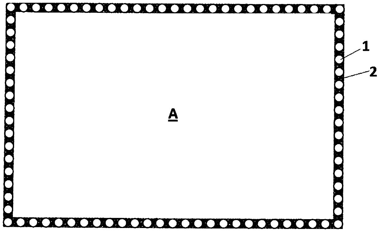
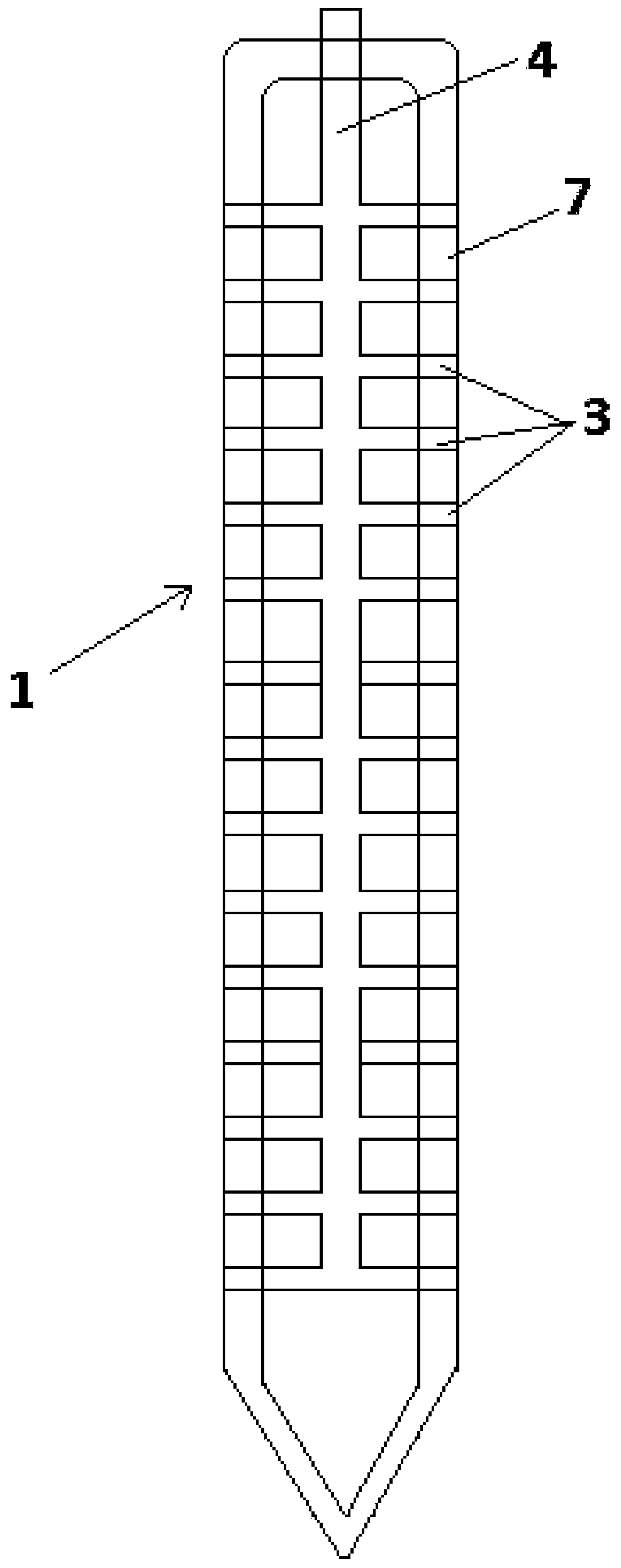
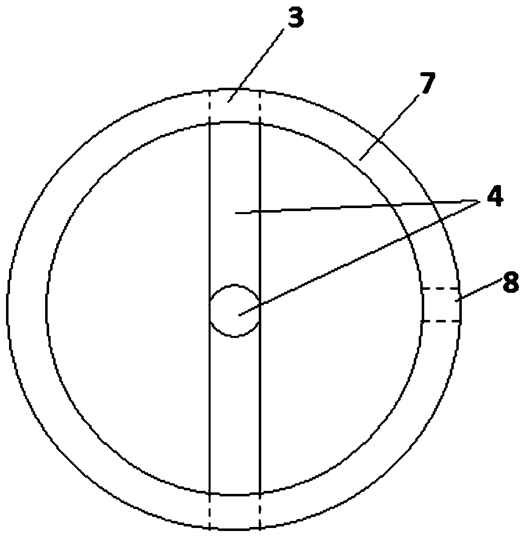
[0037] Such as figure 1 As shown, the foundation pit support composite retaining wall provided in this embodiment includes: several tubular piles 1 with hollow structures arranged in the circumferential direction; the connecting structure 2 is connected with two adjacent tubular piles 1 to form A circumferentially closed retaining wall; wherein, at least one of the pipe walls at the lower part of the pipe pile is provided with a water pump facing the inner side of the foundation pit A and communicating with the inner soil body of the foundation pit and the hollow structure structure, and the pumping structure is suitable for introducing groundwater inside the foundation pit into the hollow structure of the pipe pile. The connection structure 2 may be a cement-soil retaining wall part, located between two adjacent pipe piles, and connected with the pipe piles; Corresponding grouting structure. Such as figure 2 As shown, the pipe pile can be open at the upper end and sealed ...

Embodiment 2

[0043] The present invention also provides a construction method for foundation pit supporting composite retaining wall, such as Figure 6 - Figure 8 As shown, it includes: a. Using a piling device to insert several pipe piles with a hollow structure into the soil at the pile positions arranged in the circumferential direction until a predetermined depth, wherein, such as Figure 6 As shown, the pipe wall of the pipe pile is provided with a grouting structure corresponding to the part of the cement-soil retaining wall; at least one pipe wall at the lower part of the pipe pile 1 is provided with a , and a pumping structure connected with the inner soil body of the foundation pit A and the hollow structure, suitable for introducing groundwater located inside the foundation pit into the hollow structure of the pipe pile; b. using grouting The equipment injects cement slurry 12 into the soil through the grouting structure to form a cement-soil structure connected to the pipe pil...


PUM


Abstract

The invention provides a foundation pit supporting composite retaining wall. The foundation pit supporting composite retaining wall comprises a plurality of tubular piles which are arranged in the circumferential direction and are of hollow structures, and a connecting structure connected with two adjacent tubular piles to form a circumferentially closed retaining wall, wherein the pipe wall of the lower portion of at least one tubular pile is provided with a water pumping structure which faces the inner side of a foundation pit and communicates with a soil body on the inner side of the foundation pit and the hollow structure, and the water pumping structure is suitable for guiding underground water located on the inner side of the foundation pit into the hollow structure of the tubular piles. By means of the structure, the overall construction operation is simple, the construction time is short, due to the fact that the connecting structure is arranged between adjacent two tubular piles serving as the main soil retaining part of the retaining wall, the number of pile bodies can be reduced, recycling is convenient, and cost saving is facilitated; and furthermore, due to the fact that the water pumping structure is arranged, the purpose of pumping underground water on the inner side of the foundation pit is achieved.

Description

technical field [0001] The invention relates to a construction method of a retaining wall in the field of foundation pit support, in particular to a foundation pit support composite retaining wall and a construction method thereof. Background technique [0002] The cement-soil retaining wall in the prior art is usually drilled into the soil body through the drill pipe and drill bit of the drilling rig, and then the cement slurry is injected into the soil body through the grouting pipe to form the cement-soil pile body; For the cement-soil pile retaining wall, the pile holes drilled by the drilling rig need to have overlapping parts. However, although the pure cement-soil occlusal pile retaining wall has good water-stop performance, its ability to retain soil is poor; The soil capacity of the concrete piles is the reason for the retaining wall. Concrete pile retaining wall has better soil retaining capacity because of its strong structure and better compressive performance....

Claims


Application Information

Patent Timeline
Patent Type & Authority Applications(China)
IPC IPC(8): E02D17/04E02D29/02E02D5/28E02D19/10
Inventor 刘小檀刘献刚
Owner 刘小檀
Why Eureka
Try Eureka