Heat isolating structure of heating core

A heating core, electric heating tube technology, applied in fluid heaters, lighting and heating equipment, etc., can solve the problems of reduced service life of containers, reduced product competitiveness, and increased material costs.

Pending Publication Date: 2020-02-18
ZHENJIANG DONGFANG ELECTRIC HEATER
View PDF0 Cites 1 Cited by
  • Summary
  • Abstract
  • Description
  • Claims
  • Application Information

AI Technical Summary

Problems solved by technology

[0002] Normally, the circulation heater structure is designed with reference to the GB151 heat exchanger, but the heater is different from the heat exchanger. The heating tube body is constantly dissipating heat, and the surface of the heating tube is heated when the flow rate is low. The temperature will be much higher than the temperature of the heating medium, and the heating tube is closer to the container shell, generally about 8~12mm away from the inside of the shell, and the high temperature will be tran...

Method used


Image

  • Heat isolating structure of heating core
  • Heat isolating structure of heating core
  • Heat isolating structure of heating core

Examples


Embodiment Construction

[0014] The heat insulation structure of the heating core of the present invention will be further described in detail below in conjunction with the accompanying drawings and specific embodiments.

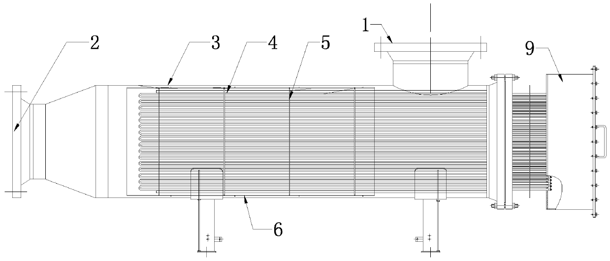
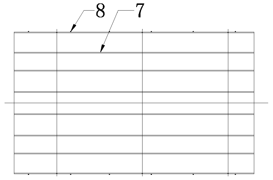
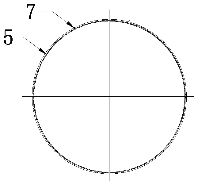
[0015] As shown in the figure, the heat insulation structure of the heating core of the present invention includes a container 3 with a medium inlet 1 and a medium outlet 2 and an electric heating tube 4 located in the container, and the electric heating tube 4 passes through a plurality of support nets (baffles) 5 Carry out positioning installation, the specific installation structure is as follows figure 1 As shown, the electric heating tube is positioned and fixed as a whole through a series of evenly arranged support nets. The electric heating tube 4 is fixed and installed through the support member 5 to form an integral heating core structure. The electric heating tube 4 and the container 3 There is a heat insulating cylinder 6, the two sides of the heat insulating cylinder are...


PUM


Abstract

The invention discloses a heat isolating structure of a heating core. The heat isolating structure comprises a container with a medium inlet and a medium outlet and an electric heating tube located inthe container. The electric heating tube is positioned and mounted by a plurality of supporting parts. A heat isolating barrel is placed between the electric heating tube and the container. The heatisolating barrel is welded and fixed to the peripheries of the supporting parts. The heat isolating barrel avoids the medium inlet, and a heating medium flows in from the medium inlet to heat throughthe electric heating tube in the heat isolating barrel. By adopting the structure, the temperature of a medium is increased, and meanwhile, high-temperature heat diffused by the electric heating tubeis blocked by the heat isolating barrel, so that temperature transferred to the inner wall of the container is reduced. Purposes of reducing the designed using temperature of the container, decreasingthe thickness of the container, improving the safety and prolonging the service life are achieved. The energy sources and the material cost are also saved. Therefore, the heat isolating structure meets the demand in reducing the temperature, transferred to container shell, on the surface of the heating tube under the circumstance of relatively high temperature of the heating medium.

Description

technical field [0001] The invention relates to a circulating heater structure, in particular to a heating core heat insulation structure. Background technique [0002] Normally, the circulation heater structure is designed with reference to the GB151 heat exchanger, but the heater is different from the heat exchanger. The heating tube body is constantly dissipating heat, and the surface of the heating tube is heated when the flow rate is low. The temperature will be much higher than the temperature of the heating medium, and the heating tube is closer to the container shell, generally about 8~12mm away from the inside of the shell, and the high temperature will be transmitted to the surface of the shell. The container shell is designed according to GB150 and TSG21-2016 In this situation, it is necessary to increase the design temperature, resulting in an increase in the thickness of the container shell and an increase in the flange level. More seriously, the original design...

Claims


Application Information

Patent Timeline
IPC IPC(8): F24H9/00F24H9/18
CPCF24H9/00F24H9/18
Inventor 杨萍徐金华
Owner ZHENJIANG DONGFANG ELECTRIC HEATER
Why Eureka
Try Eureka