Ultrasonic-knife conduction rod and ultrasonic knife

An ultrasonic knife and transmission rod technology, applied in the field of ultrasonic surgical knives, can solve the problems of sacrificing the resonance phase tolerance, increasing the input ultrasonic wave of the knife rod, and unstable sound wave conduction, achieving reasonable sound gain, realizing acoustic characteristics, and good vibration shape. Effect

Active Publication Date: 2020-02-21
北京锐诺医疗技术有限公司
View PDF15 Cites 1 Cited by
  • Summary
  • Abstract
  • Description
  • Claims
  • Application Information

AI Technical Summary

Problems solved by technology

Setting the gain step at the half-wavelength node increases the vibration amplitude of the input ultrasonic wave from the cutter bar, and the larger the vibration amplitude, the greater the friction between the sound wave and the solid medium during propagation, and the more obvious the energy loss of the sound wave , which leads to the instability of sound wave conduction, sacrificing the phase tolerance of resonance

Method used


Image

  • Ultrasonic-knife conduction rod and ultrasonic knife
  • Ultrasonic-knife conduction rod and ultrasonic knife
  • Ultrasonic-knife conduction rod and ultrasonic knife

Examples


Embodiment Construction

[0036] The technical solutions in the embodiments of the present invention will be clearly and completely described below in conjunction with the accompanying drawings in the embodiments of the present invention. Obviously, the described embodiments are part of the embodiments of the present invention, not all of them.

[0037] Elements / components with the same or similar numbers used in the drawings and embodiments are used to represent the same or similar parts. And the drawings are only schematic, and the elements therein need not be in proportion.

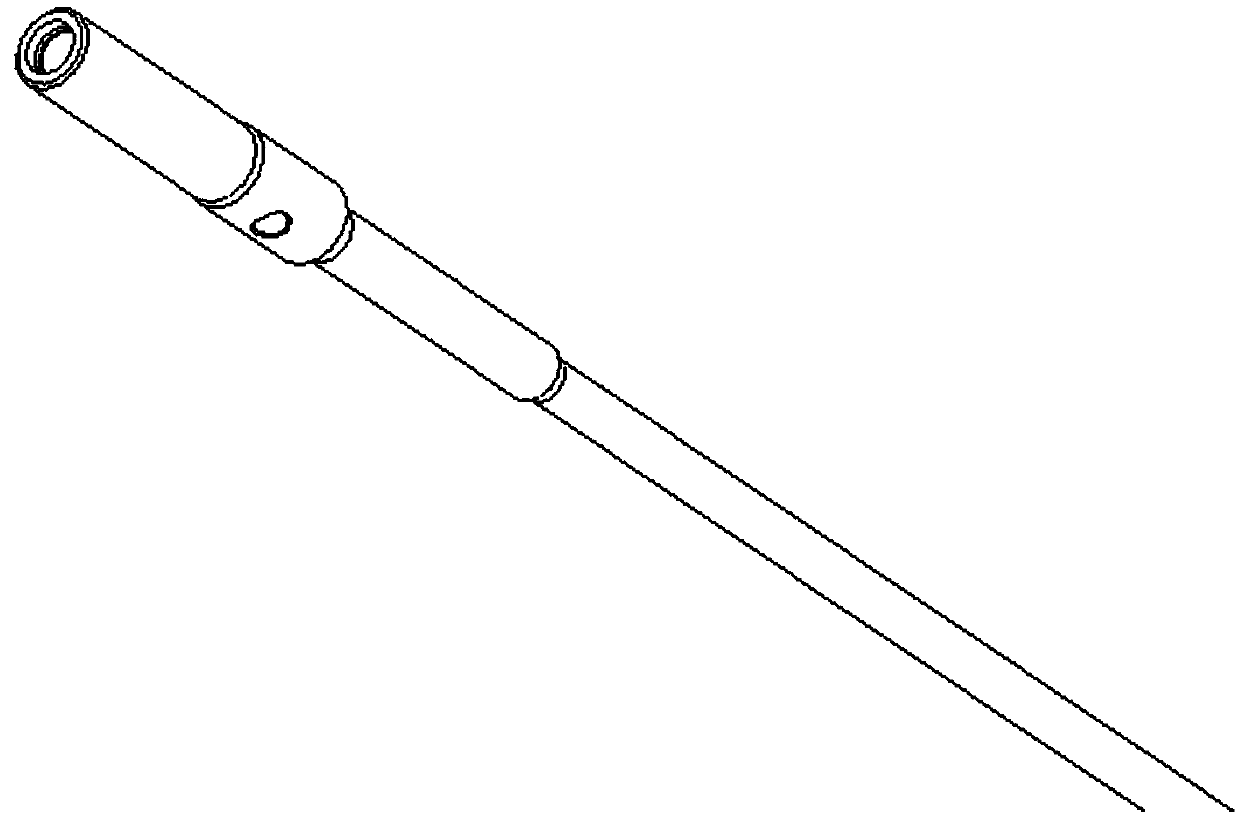
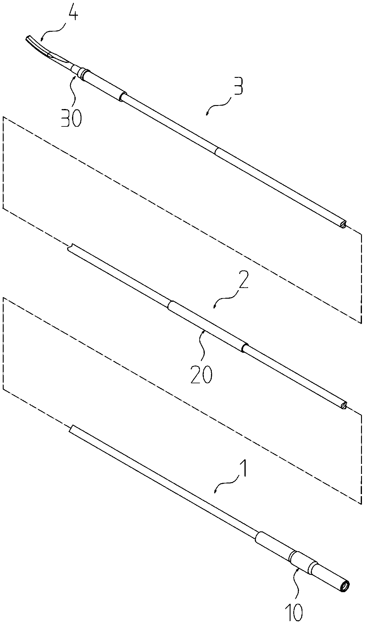
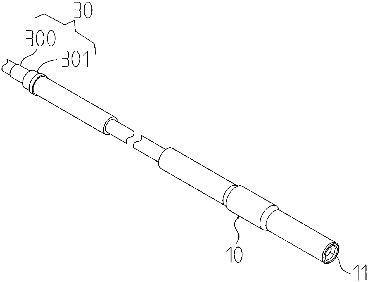
[0038] figure 2 Illustrates an exploded structural schematic diagram of the entire ultrasonic knife conductive rod according to an embodiment of the present invention. Such as figure 2 As shown, the conductive rod of the ultrasonic knife of the embodiment of the present invention includes a proximal rod 1, a middle rod 2 and a distal rod 3 that are connected in sequence. One end of the proximal rod 1 is connected to the ultrasonic...


PUM


Abstract

The invention discloses an ultrasonic-knife conduction rod and an ultrasonic knife. The conduction rod comprises a near rod body, a middle rod body and a far rod body which are connected in sequence,wherein one end of the near rod body is connected with an ultrasonic transducer, and the other end of the near rod body is connected with the middle rod body; one end of the far rod body is connectedwith the middle rod body, and the other end of the far rod body is connected with a knife head; sound waves are transmitted from the end, connected with the ultrasonic transducer, of the near rod body; a bulge structure is arranged on the outer surface of the near rod body in the circumferential direction; gain steps are arranged on the outer surface of the middle rod body and / or the far rod bodyin the circumferential direction; and the ultrasonic knife comprises the conduction rod. Compared with the prior art, the ultrasonic-knife conduction rod has the advantages that the phase tolerance and amplitude of resonance can be remarkably improved, and the energy loss of the sound waves can be reduced; the impedance of the conduction rod is smaller, so that the ultrasonic knife has a more stable working state and higher-efficiency output, and the ultrasonic-knife conduction rod can be suitable for general occasions and can also be suitable for complex working environments, thereby having awide application prospect.

Description

Technical field [0001] The present invention relates to the technical field of ultrasonic scalpel. More specifically, the present invention relates to an ultrasonic knife conduction rod and an ultrasonic knife. Background technique [0002] Ultrasonic scalpel (ultrasonic scalpel) is a new type of surgical instrument. Compared with traditional electric scalpel, it has obvious advantages, such as precise cutting, hemostasis, less thermal damage, short operation time, and can be used for important organs, There is very little smoke and coking, ensuring a clear vision during the operation, no current passing through the human body, and any substantial tissue other than bone tissue can be removed. As the ultrasonic knife is used more and more, the performance requirements of the ultrasonic knife are getting higher and higher. [0003] The resonance characteristics of the ultrasonic knife vibration system, including the resonance frequency, resonance impedance and resonance amplitude, d...

Claims


Application Information

Patent Timeline
Patent Type & Authority Applications(China)
IPC IPC(8): A61B17/32
CPCA61B17/320068A61B2017/320069A61B2017/320075A61B2017/320082
Inventor 洪文亮张学武
Owner 北京锐诺医疗技术有限公司
Why Eureka
Try Eureka