
Suction device

A technology of adsorption device and adsorption part, which is applied in the direction of transportation and packaging, load hanging components, chucks, etc., can solve the problems of workpiece falling off and position deviation, and achieve the effect of preventing falling off

Active Publication Date: 2020-02-21
SMC CORP
View PDF6 Cites 0 Cited by
  • Summary
  • Abstract
  • Description
  • Claims
  • Application Information

AI Technical Summary

Problems solved by technology

Thus, for example, when the inertial force acting on the workpiece is large relative to the adsorption force of the adsorption pad, the workpiece slides relative to the adsorption pad to cause a positional shift, or when the workpiece is conveyed at a high speed. In this case, the workpiece may fall off from the suction pad

Method used


Image

  • Suction device
  • Suction device
  • Suction device

Examples


Embodiment Construction

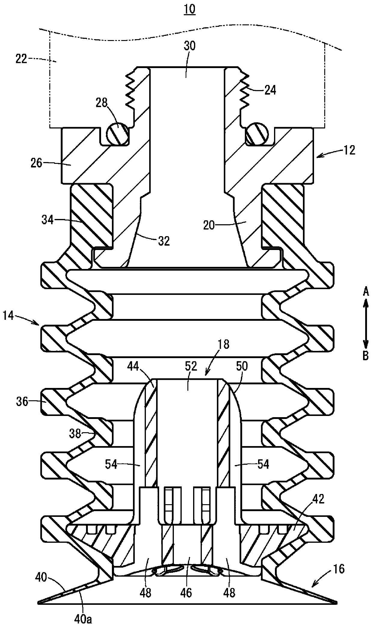
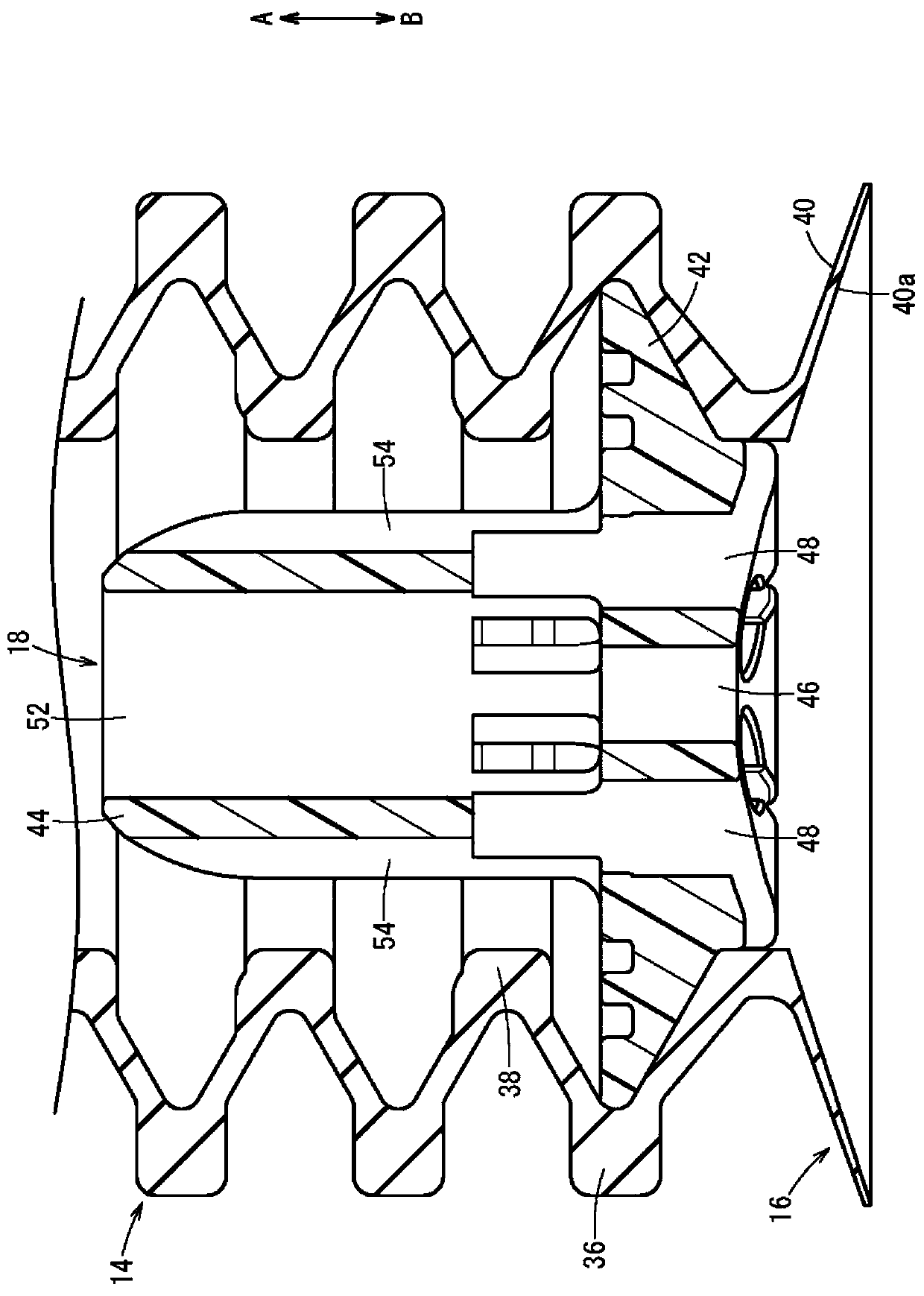
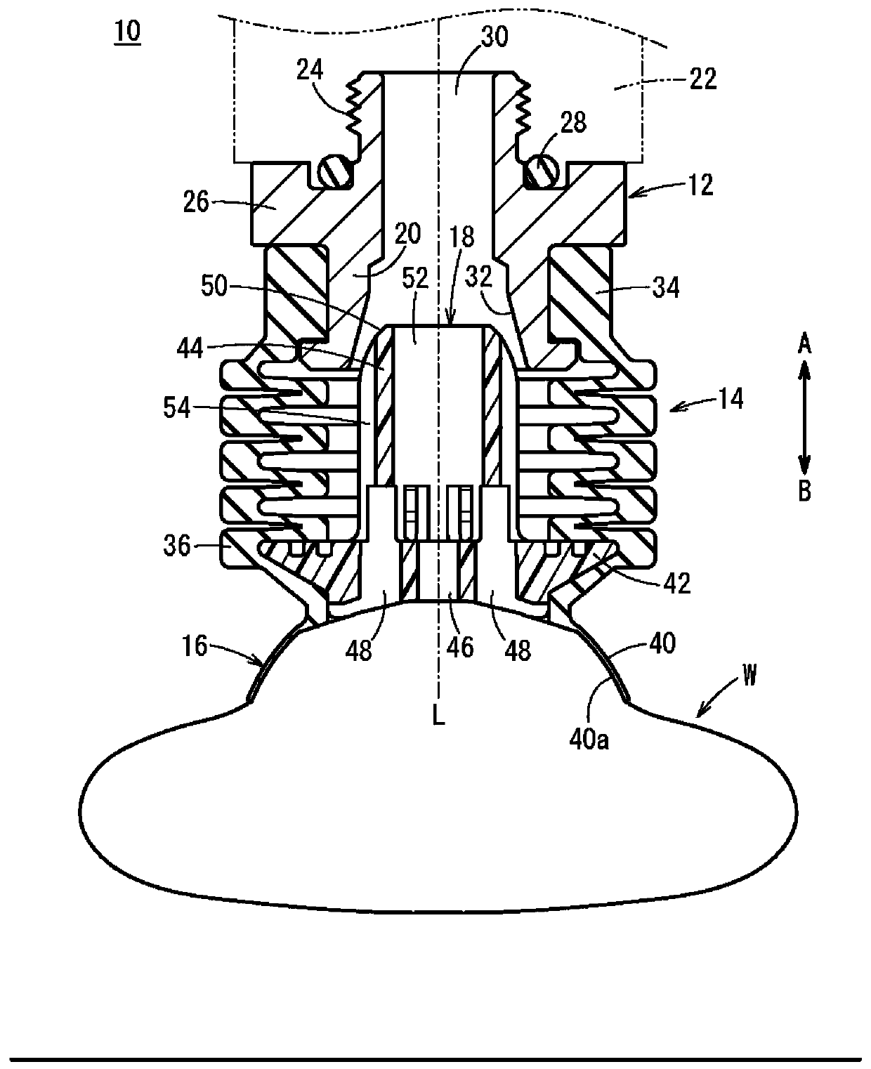
[0019] Such as Figure 1 ~ Figure 4 As shown, the suction device 10 includes: an adapter (main body) 12 connected to a negative pressure supply device (not shown) through piping, a bellows 14 connected to the lower end of the adapter 12, and a bellows 14 formed on the bellows 14. A pad portion (adsorption portion) 16 at the lower end portion (front end), and an attachment (tilting member) 18 accommodated inside the bellows 14 and the pad portion 16 .

[0020] The adapter 12 is formed, for example, in a cylindrical shape made of a metal material, and has a connecting portion 20 connected to the bellows 14 at its lower end, and a threaded portion 24 connected to a joint 22 at its upper end. In addition, a flange portion 26 protruding in a direction perpendicular to the axial direction (directions of arrows A and B) is formed between the coupling portion 20 and the threaded portion 24 in the adapter 12 .

[0021] In addition, a seal ring 28 is attached to the end surface of the ...


PUM


Abstract

A suction device (10) includes an adapter (12) having in the interior thereof a supply passage (30) to which a negative pressure fluid is supplied, a bellows (14) connected to a distal end of the adapter (12), and a pad member (16) disposed at a distal end of the bellows (14) and to which a workpiece (W) is attracted under suction. In addition, the suction device (10) attracts the workpiece (W) under suction by a negative pressure fluid which is supplied to the pad member (16) through the supply passage (30) and the bellows (14). An attachment (18) which is capable of being tilted with respectto the axis of the bellows (14) is provided in the interior of the bellows (14). In the attachment (18), a main body portion thereof (42) is disposed in facing relation to a suction surface (40a) ofa skirt (40), and a shaft portion (44) is inserted into the supply passage (30) at a time that the workpiece (W) is attracted under suction.

Description

technical field [0001] The invention relates to an adsorption device capable of absorbing and transporting workpieces under the action of supplying negative pressure fluid. Background technique [0002] Conventionally, there is known a suction device for sucking and conveying workpieces by using a supplied negative pressure fluid. In this suction device, for example, workpieces inclined with respect to a suction pad are sometimes sucked. In such cases, sometimes the suction The pad will not be in close contact with the workpiece, so that the negative pressure fluid cannot effectively act on the workpiece, resulting in poor adsorption. [0003] Therefore, in order to solve the above-mentioned problems, for example, in the suction device disclosed in Japanese Utility Model Publication No. 5-35973, a hollow connecting screw is connected to the lower end of the mounting member, and a spherical ball joint is provided at the lower end. In addition, the ball bracket holding the su...

Claims


Application Information

Patent Timeline
Patent Type & Authority Applications(China)
IPC IPC(8): B65G47/90
CPCB65G47/90B25J15/0616B66C1/0212B66C1/0293B66C1/0206B65G47/91B25J15/0683B65G2201/0238
Inventor 中山徹杉山亨宫崎则行斋藤优后藤幸也
Owner SMC CORP
Features
  • Generate Ideas
  • Intellectual Property
  • Life Sciences
  • Materials
  • Tech Scout
  • Unparalleled Data Quality
  • Higher Quality Content
  • 60% Fewer Hallucinations
Learn More