Novel efficient cuff ironing press
A pressing machine, high-efficiency technology, applied in the direction of wrinkle-removing and flattening equipment, washing equipment, textiles and papermaking, etc., can solve the problems that the production efficiency cannot meet the market demand, and achieve the effect of avoiding overpressure and improving the quality of pressing
- Summary
- Abstract
- Description
- Claims
- Application Information
AI Technical Summary
Problems solved by technology
Method used
Image
Examples
Embodiment 1
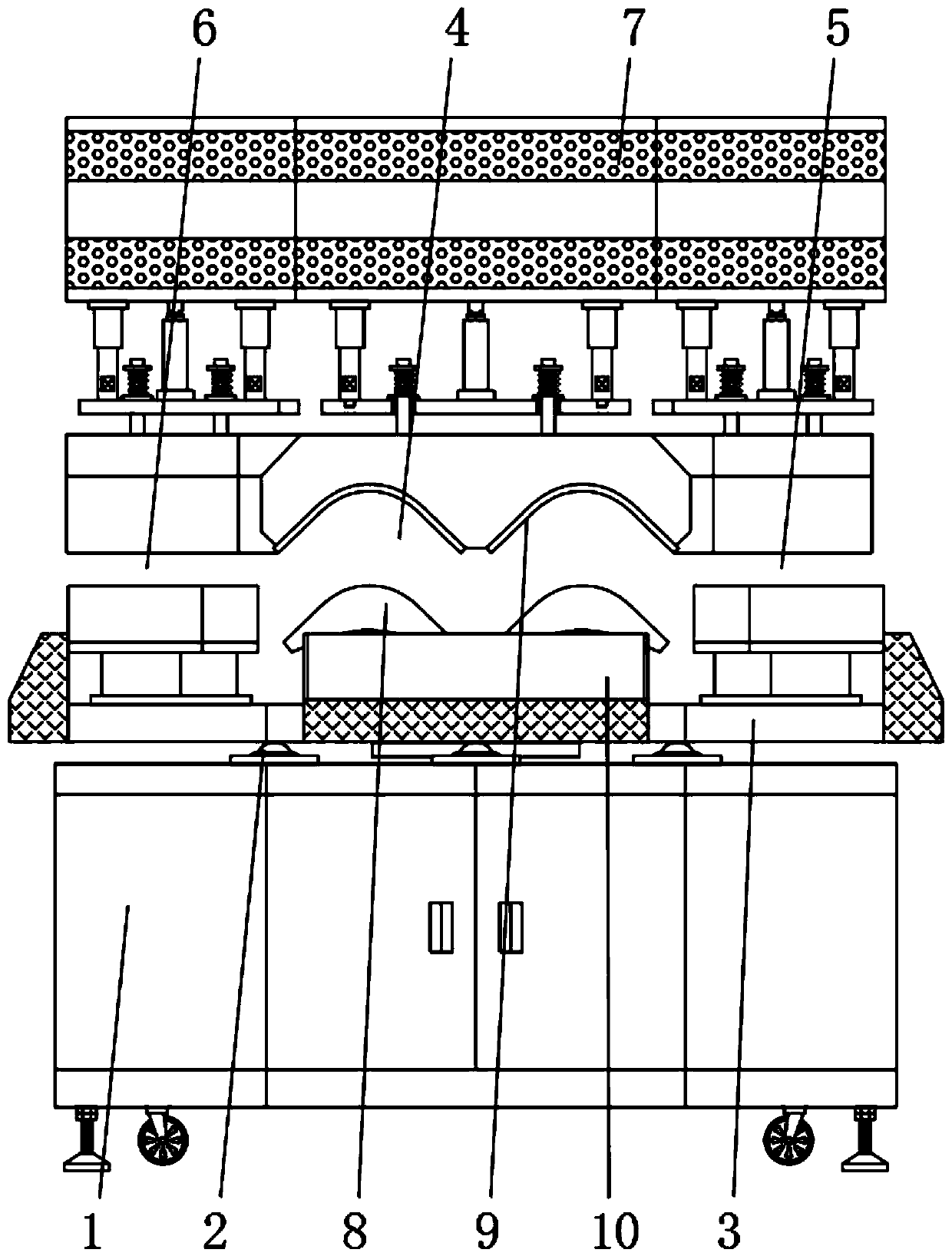
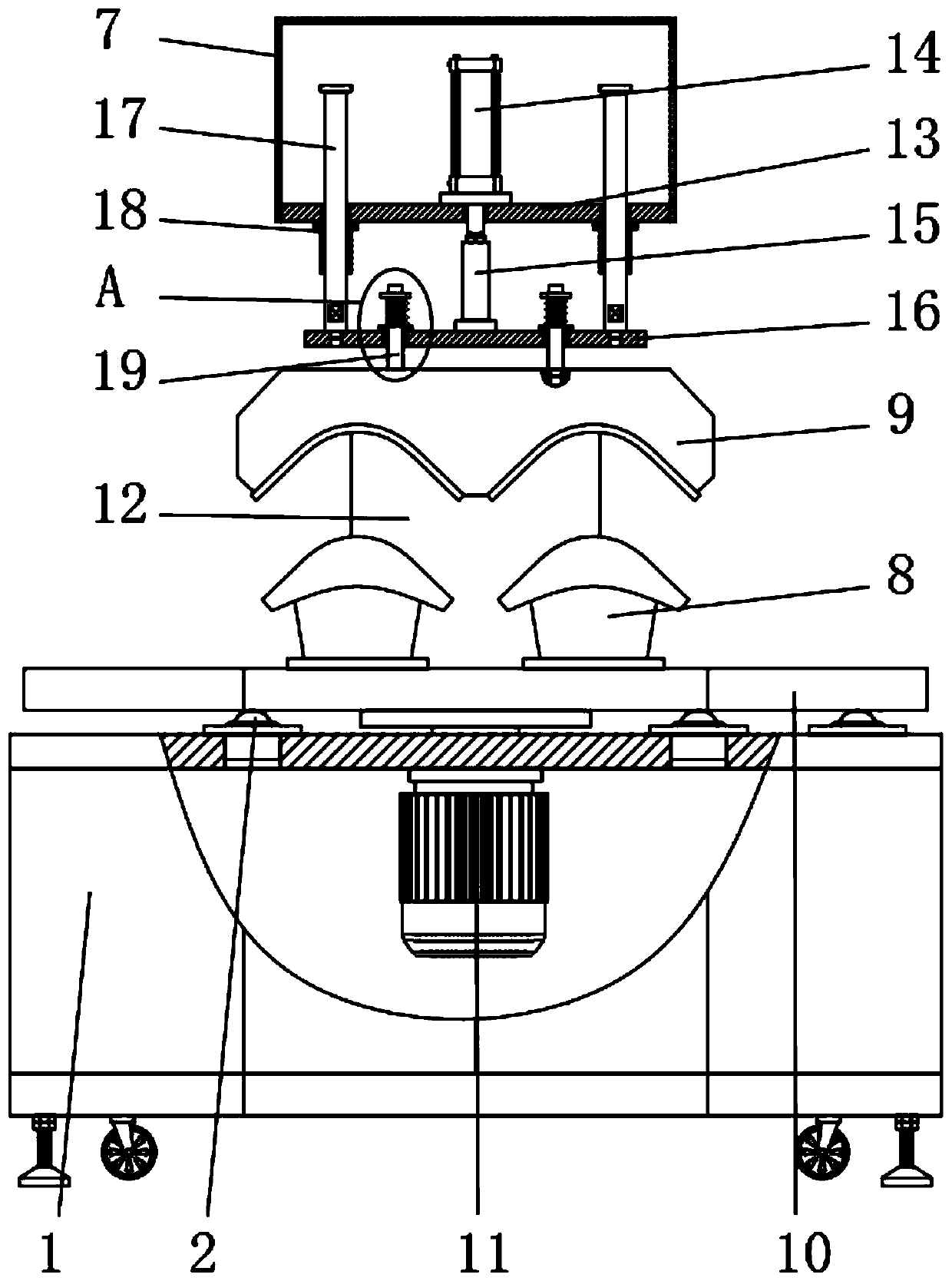
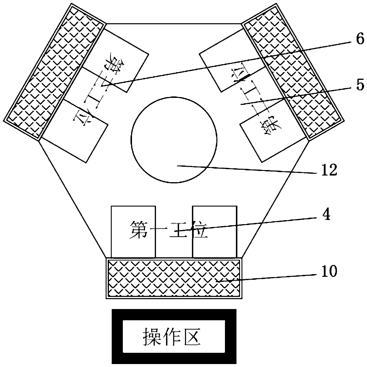
[0030] Embodiment one, with reference to Figure 1-3 , a new type of high-efficiency cuff pressing machine, including a base 1 and a rotating disc 3, a rotating motor 11 is installed in the middle of the base 1, and the output shaft of the rotating motor 11 is connected to the rotating disc 3 above the base 1 in rotation, and the rotating disc 3 The first station 4, the second station 5 and the third station 6 are distributed in a ring shape, and the composition and structure of the first station 4, the second station 5 and the third station 6 are the same, and the first station 4 A fixed mold 8 is fixed on the upper surface of the rotating disk 3, and a lifting mold 9 is arranged directly above the fixed mold 8, and a transition plate 16 is arranged above the lifting mold 9, and the middle position of the upper surface of the transition plate 16 is connected to the lifting cylinder through the cylinder joint 15. 14 is connected, and the lifting cylinder 14 is fixed on the upp...
Embodiment 2
[0031] Embodiment two, refer to figure 2 and Figure 4 , the lifting mold 9 is slidingly connected with the bushing 20 embedded on the transition plate 16 through the guide post 19, and the guide post 19 is sleeved with an elastic member 21, the elastic member 21 is welded to the connecting piece 22, and the connecting piece 22 is connected by a screw 23 It is fixedly connected with the upper end of the guide post 19, and the bush 20 adopts JFBB flanging self-lubricating oil-free bearing. There are multiple guide posts 19 and elastic parts 21, and the plurality of guide posts 19 and elastic parts 21 are vertical to the transition plate 16. The central line is symmetrically distributed, and the lifting mold 9 is elastically connected to the transition plate 16 through the guide column 19 and the elastic member 21. When the lifting cylinder 14 drives the lifting mold 9 to squeeze the shirt cuff on the fixed mold 8, the lifting mold 9 first presses Hold the shirt cuffs, and the...
Embodiment 3
[0032] Embodiment three, refer to figure 1 and 5 , a plurality of universal ball bearings 2 are installed on the upper surface of the base 1, and the plurality of universal ball bearings 2 are annularly distributed about the rotating column 12, and the first station 4, the second station 5 and the third station 6 are all set There are two fixed molds 8, and the two fixed molds 8 of each station are connected with a holding basket 10, which is used to support the shirt and prevent the shirt from slipping. The weight of the basket 10 is supported by the universal ball to the rotating disk 3, which can improve the stability and load-bearing capacity of the rotating disk 3 when rotating, and prevent the lifting cylinder 14 from driving the lifting mold 9 from swinging at each station when the shirt is pressed.
[0033]Working principle: move the device to a reasonable area, connect the power supply and air source, and adjust it to normal use. When working, the operator is located...
PUM
 Abstract
Description
Claims
Application Information
 - R&D
- Intellectual Property
- Life Sciences
- Materials
- Tech Scout
- Unparalleled Data Quality
- Higher Quality Content
- 60% Fewer Hallucinations
Browse by: Latest US Patents, China's latest patents, Technical Efficacy Thesaurus, Application Domain, Technology Topic, Popular Technical Reports.
© 2025 PatSnap. All rights reserved.Legal|Privacy policy|Modern Slavery Act Transparency Statement|Sitemap|About US| Contact US: help@patsnap.com


