Supercharge Your Innovation With Domain-Expert AI Agents!

Construction method for steel ladle beam supporting structure

A construction method and beam support technology, applied in the direction of pillars, columns, pier columns, etc., can solve the problems that the joints between the main section steel and the support section steel cannot be filled, it is difficult to control the uniformity of concrete materials, and the difference in concrete height and density. Achieve the effect of improving construction efficiency, reducing construction difficulty and ensuring consistency

Active Publication Date: 2020-02-21
TIANJIN WUQING DISTRICT CONSTRUCTION ENG CORP
View PDF5 Cites 0 Cited by
  • Summary
  • Abstract
  • Description
  • Claims
  • Application Information

AI Technical Summary

Problems solved by technology

According to the current pouring process, it is difficult to observe the height to which the concrete is poured. If the amount of pouring is too small, the joint between the main section steel and the supporting section steel cannot be filled. The uniformity of the concrete material leads to the difference in the height and density of the concrete in the multiple supporting steel, which affects the supporting performance of the final supporting structure

Method used


Image

  • Construction method for steel ladle beam supporting structure
  • Construction method for steel ladle beam supporting structure
  • Construction method for steel ladle beam supporting structure

Examples


Embodiment 1

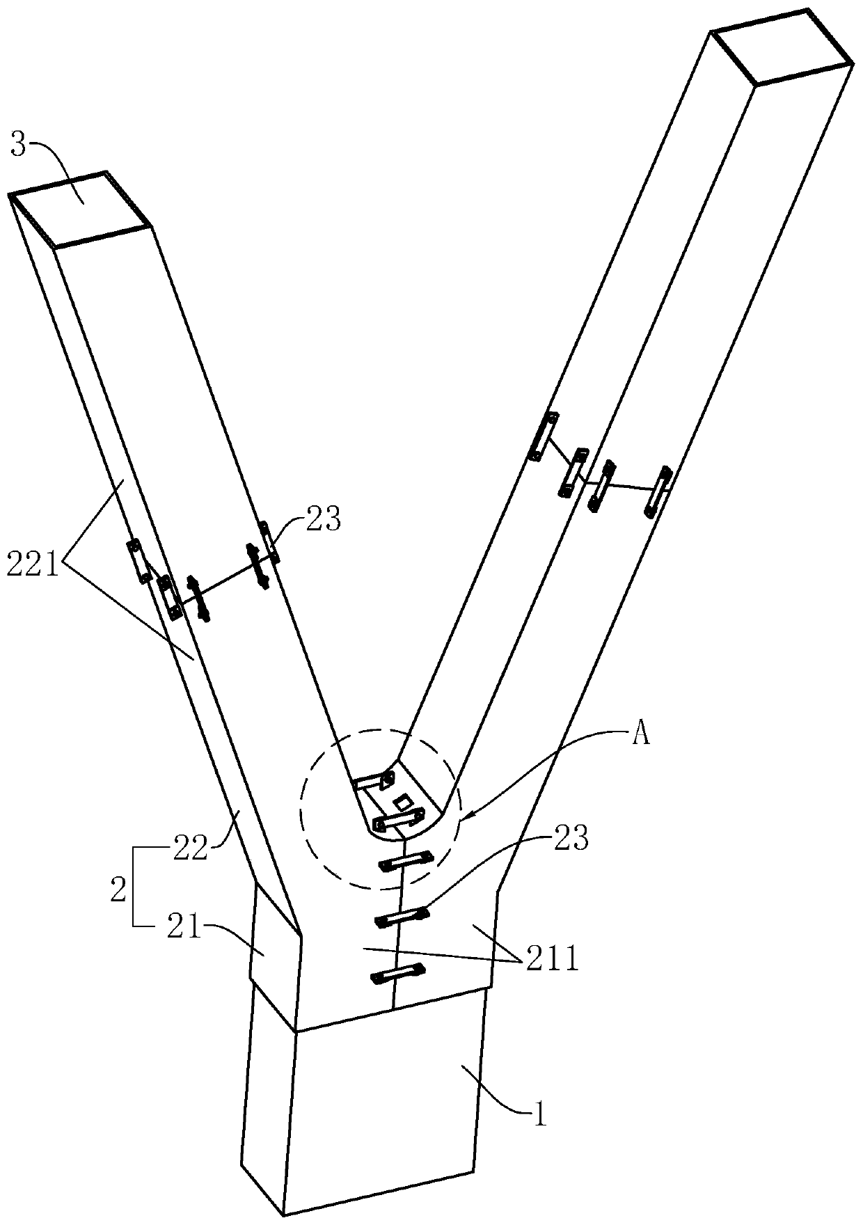
[0043] Such as figure 1As shown, this embodiment introduces a ladle column support structure, which includes a main concrete structural column 1 and an outsourcing steel section 2. The main concrete structural column 1 is integrally connected above the ground, and above the main concrete structural column 1 is integrally connected with two The above supporting columns 3 are introduced in this embodiment by taking two supporting columns 3 as an example. The outsourcing section steel 2 includes main section steel 21 and support section steel 22 , the main section steel 21 is wrapped on the outside of the main concrete structural column 1 , and the support section steel 22 is wrapped on the outside of the support column 3 . The ladle column support structure of this structure uses a main concrete structural column 1 to support multiple support columns 3, and sets the main section steel 21 to wrap the main concrete structural column 1, and sets the support section steel 22 to wrap...

Embodiment 2

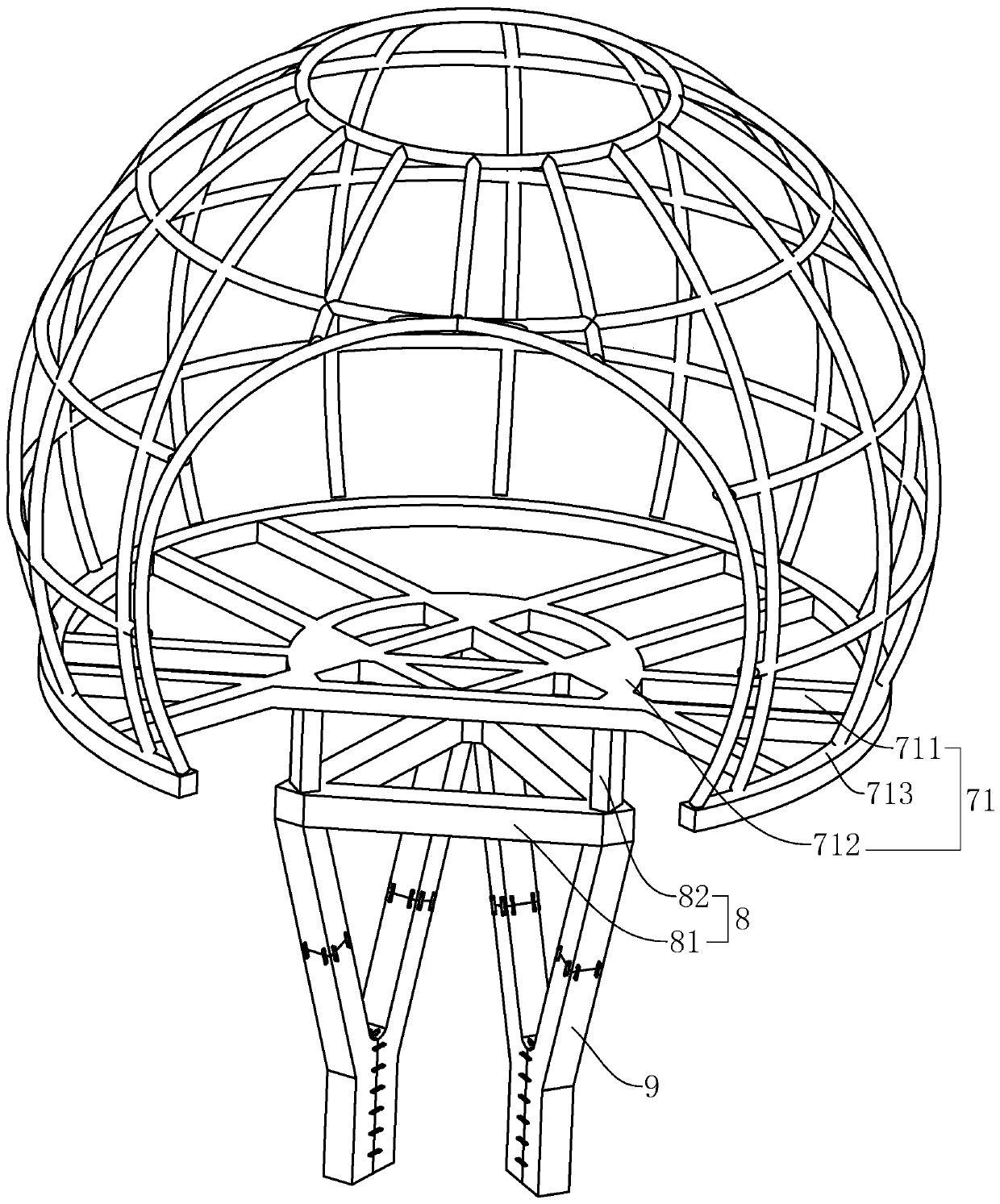
[0052] Such as image 3 As shown, this embodiment introduces a lecture hall structure, including a ladle column support structure 9, a viewing platform 8 and a lecture hall 7, the viewing platform 8 is located above the ladle column support structure 9, and the lecture hall 7 is located on the viewing platform 8, the structure of the ladle column support structure 9 is as described in Embodiment 1. The ladle column support structure 9 includes two, and the two ladle column support structures 9 are used to stably support the viewing platform 8, and the occupied support space Smaller, viewing platform 8 can provide viewing space and the number of floors, while lecture hall 7 is the main viewing point.

[0053] Such as image 3 As shown, structurally, the lecture hall 7 includes a bottom support structure 71 and a top support structure 72, and the bottom support structure 71 includes criss-cross second support beams 711 and arc-shaped third support beams 712 and fourth support b...

Embodiment 3

[0056] This embodiment introduces a construction method of a steel clad beam support structure, including the following steps.

[0057] S1. Binding steel bars, installing the main section steel 21 and the support section steel 22, the specific steps are as follows.

[0058] S11. Combine figure 1 and Figure 4 As shown, at first the reinforcement of the main concrete structural column 1 is bound, and the formwork is supported, and the lower part of the main concrete structural column 1 is poured with concrete;

[0059] S12, demoulding, binding the reinforcing bar of support column 3;

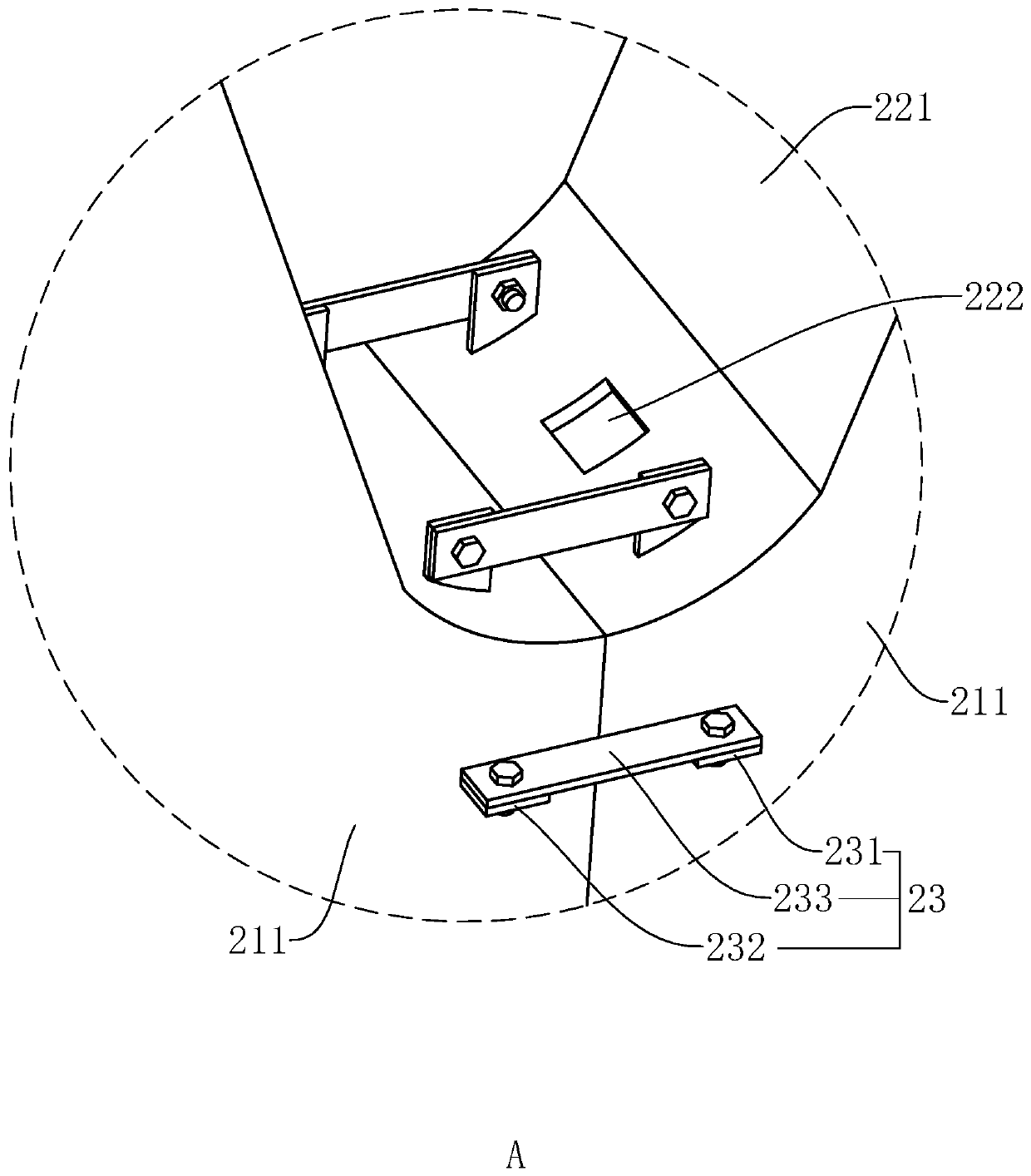
[0060] S13. Dividing the parting surface of the main section steel 21 along the vertical direction into a plurality of main section steel splices 211, the main section steel splices 211 are welded together with the lower end of the support section steel 22, and the support section steel 22 is respectively socketed on different supports On the outer side of the steel bar of column 3, the main s...


PUM


Abstract

The invention relates to a steel-reinforced concrete column, in particular to a construction method for a steel ladle beam supporting structure. The construction method comprises the following steps of S1, binding a reinforcing steel bar and mounting main profile steel and supporting profile steel; S2, forming a dust discharging hole above a connecting node of the main profile steel and the supporting profile steel, pouring concrete into the main profile steel and the supporting profile steel and pouring concrete to the node of the main profile steel and the supporting profile steel, and forming a main concrete structural column and a node of a supporting column and the main concrete structural column; S3, continuously lengthening the reinforcing steel bar which binds the supporting columnand the supporting profile steel; and S4, pouring and forming the supporting column. According to the construction method, after the main profile steel and the supporting profile steel are mounted, the position of the poured concrete can be observed through the dust discharging hole when the concrete is poured into the node of the supporting profile steel and the main profile steel and excessivepoured concrete can flow out from the dust discharging hole, so that the consistence of the pouring performance of the main concrete structural column and the supporting column at the node is guaranteed, and the stability of the supporting structure is enhanced.

Description

technical field [0001] The invention relates to a steel concrete column, in particular to a construction method of a steel clad beam support structure. Background technique [0002] In today's society, in order to meet the housing pressure in the city and meet the needs of people's office space, many high-rise buildings have been built in urban areas. In order to improve the strength of high-rise buildings, usually in the process of building high-rise buildings, steel concrete columns are used as the skeleton of high-rise buildings, thereby improving the strength of high-rise buildings and improving safety performance. [0003] The shaped steel concrete column is also called the ladle column structure. It is a steel structure added to the outside of the structural column. During the forming process, the section steel structure can act as a formwork, which greatly saves the formwork system. At the same time, due to the setting of the section steel structure, the strength, st...

Claims


Application Information

Patent Timeline
Patent Type & Authority Applications(China)
IPC IPC(8): E04C3/32E04C3/34
CPCE04C3/32E04C3/34
Inventor 侯大海田文刚王福海于海龙薄振东
Owner TIANJIN WUQING DISTRICT CONSTRUCTION ENG CORP
Features
  • R&D
  • Intellectual Property
  • Life Sciences
  • Materials
  • Tech Scout
  • Unparalleled Data Quality
  • Higher Quality Content
  • 60% Fewer Hallucinations
Learn More