
Safety valve inspection device

An inspection device and safety valve technology, which is applied in the field of safety valve inspection, can solve the problems of slow pressure increase of the test container, difficulty in obtaining the test container, and great influence of the temperature of the low-temperature medium, etc., and achieve the expansion of the heat exchange area and the heat exchange with the atmosphere The ability to increase self-evaporating ability and shorten the test time

Pending Publication Date: 2020-02-21
深圳市质量安全检验检测研究院
View PDF0 Cites 7 Cited by
  • Summary
  • Abstract
  • Description
  • Claims
  • Application Information

AI Technical Summary

Problems solved by technology

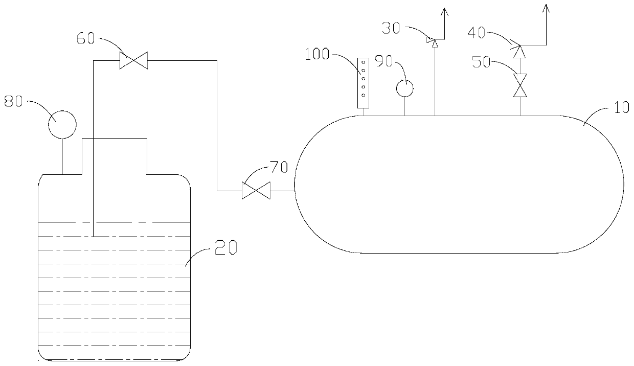
[0006] The deficiencies in the prior art are: the boosting of the test container 10 is by low-temperature liquid nitrogen passing through the outer wall of the test container 10 and the insulation material, absorbing a certain amount of heat and self-evaporating, the liquid nitrogen evaporates from liquid to gas, the volume expands, and the pressure rises to implement the verification process
[0008] 1. The pressure increase speed of the test vessel is slow and difficult to control;
[0009] 2. The temperature of low-temperature medium is greatly affected by the physical properties of self-evaporation, and it is impossible to achieve precise temperature control
Even the temperature of the medium can only be increased and cannot be lowered;
[0010] 3. The low temperature and high pressure working environment of the test vessel is difficult to obtain

Method used


Image

  • Safety valve inspection device
  • Safety valve inspection device

Examples


Embodiment Construction

[0039] In order to have a clearer understanding of the technical features, purposes and effects of the present invention, the specific implementation manners of the present invention will now be described in detail with reference to the accompanying drawings. In the following description, it should be understood that "front", "rear", "upper", "lower", "left", "right", "longitudinal", "horizontal", "vertical", "horizontal", The orientation or positional relationship indicated by "top", "bottom", "inner", "outer", "head", "tail", etc. is based on the orientation or positional relationship shown in the drawings, and is constructed and operated in a specific orientation, It is only for the convenience of describing the technical solution, but does not indicate that the referred device or element must have a specific orientation, so it should not be construed as a limitation of the present invention.

[0040] It should also be noted that terms such as "installation", "connection", ...


PUM


Abstract

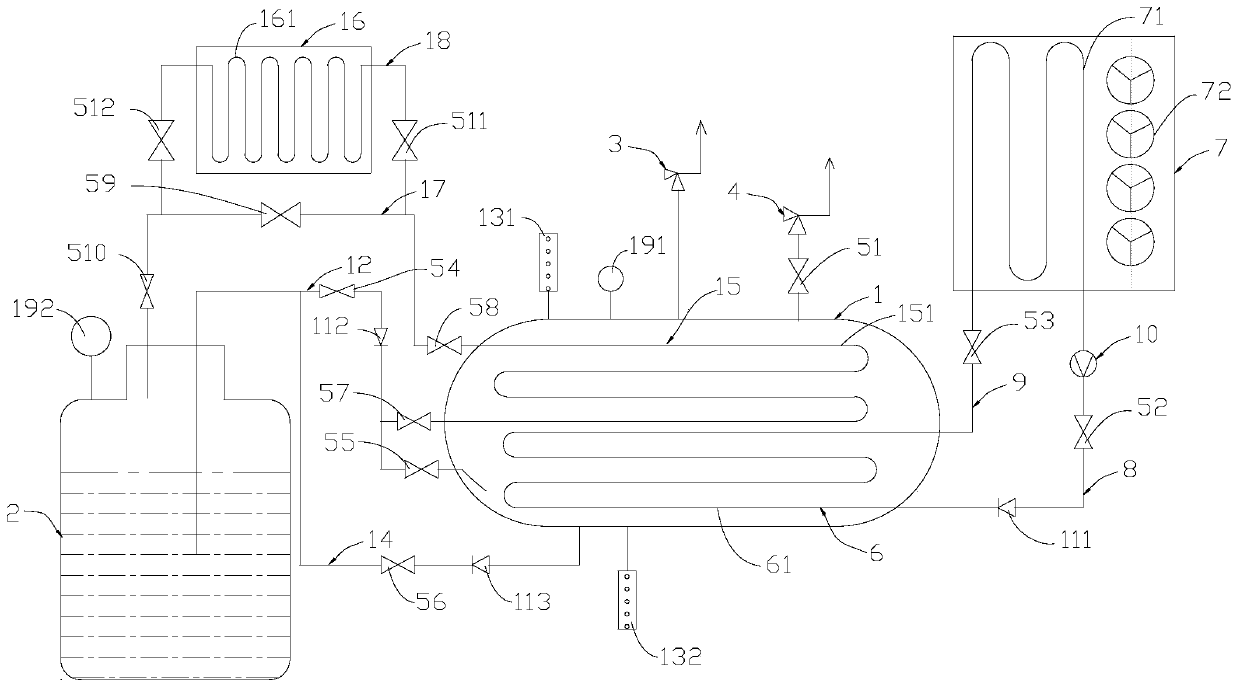
The invention relates to a safety valve inspection device. The safety valve inspection device comprises a test container and a liquid storage tank; the liquid storage tank communicates with the innercavity of the test container and can inject a low-temperature medium into the test container; the top of the test container is provided with a first control valve which communicates with the inner cavity of the test container and can be connected with a tested safety valve; a first booster is arranged in the inner cavity of the test container; the first booster comprises a first heat exchange tube; a second booster is arranged outside the test container; the second booster comprises a second heat exchange tube; the first heat exchange tube and the second heat exchange tube communicate with each other end to end, and a heat exchange circulation channel for circulating a heat exchange medium is formed; when the heat exchange medium flows through the interior of the first booster, the heat exchange medium exchanges heat with the low-temperature medium in the test container, so that the low-temperature medium absorbs the heat and expands, thus the pressure of the test container increases to verify the tested safety valve; and through the setting of the boosters, the self-evaporation capacity of the low-temperature medium is increased, the boosting rate of the test container is increased, the safety valve inspection time is shortened, the inspection efficiency is improved, and the labor cost is reduced.

Description

technical field [0001] The invention relates to the technical field of safety valve inspection, in particular to an improved safety valve inspection device. Background technique [0002] Safety valves are divided into (general) safety valves and low-temperature safety valves according to their operating temperature. According to the regulations in the "Safety Technology Supervision Regulations for Safety Valves", the type test of low-temperature safety valves should carry out the following verification items: low-temperature set pressure, low-temperature The detection and verification of the two indicators of sealing pressure. [0003] At present, the layout structure of the low temperature safety valve detection and verification device is as follows figure 1 . [0004] The working principle of the existing detection and verification device: [0005] Liquid nitrogen is fed into the test container 10 from the liquid nitrogen storage tank 20 . Generally, the low-temperatur...

Claims


Application Information

Patent Timeline
IPC IPC(8): G01M3/02G01M13/003
CPCG01M3/02G01M13/003
Inventor 孙琦
Owner 深圳市质量安全检验检测研究院
Learn More