Antenna module and terminal
An antenna module and antenna technology, applied in the direction of antenna, antenna coupling, antenna array, etc., can solve the problems of limited space of MIMO antenna module, antenna interference, affecting the efficiency of sending and receiving signals, etc.
Active Publication Date: 2020-02-21
GUANGDONG OPPO MOBILE TELECOMM CORP LTD
14 Cites 0 Cited by
AI-Extracted Technical Summary
Problems solved by technology
[0004] However, since the space occupied by each antenna in the MIMO antenna module is limited in the termin...
Method used
According to the ECC calculation method shown in formula (1), it can be obtained: the numerical value of ECC mainly depends on the impedance matching of the antenna unit, the radiation efficiency of the antenna and the isolation between the antenna units. For MIMO antennas, impedance matching and radiation efficiency have little impact on ECC, while isolation has a greater impact on the value of ECC. Therefore, in the embodiment of the present application, the coupling of the antenna elements is reduced by improving the isolation of the antenna.
Please refer to FIG. 16. FIG. 16 is a schematic diagram of a change curve of ECC related to an exemplary embodiment of the present application, as shown in FIG. 16, which includes a first curve 1610, a second curve 1620, a first sampling Point 1611, second sampling point 1621. Among them, the first curve 1610 is the ECC curve between the first antenna and the second antenna in the above-mentioned FIG. The curve of the ECC between the second antenna. It can be known from the first sampling point 1610 in Figure 16 that when the antenna module transmits a signal at a frequency of 3.6 GHz, the ECC between the first antenna and the second antenna is 0.0020521, and from the second sampling point 1604 in Figure 16 It can be seen that when the antenna module without the 180° directional coupler transmits a signal at a frequency of 3.6 GHz, the ECC between the first antenna and the second antenna is 3.9889*e-05, which is determined by the first sampling point 1611 and the second It can be known from the sampling point 1621 that the use of the 180° hybrid network can reduce the ECC between the first antenna and the second antenna, thereby reducing the isolation between the antennas. In addition, it can also be seen from the first curve 1601 and the second curve 1602 in FIG. 16 that the ECC of the first antenna and the second antenna in the antenna module using a 180° hybrid network in each frequency band of the antenna module Both are also lower than the ECC before use.
[0056] Optionally, the first antenna or the second antenna may transmit a signal of any frequency band. The 180° hybrid network 230 can provide the function of suppressing the signal sent by the first feeder, and suppress the signal from flowing into the second feeder, thereby causing coupling between the ports of the two feeders and improving the isolation between antennas .
[0064] Optionally, in the embodiment of the present application, the matching circuit may also include at least one switch, which is used to change the impedance in the matching circuit to realize impedance transformation, so that the connected antenna transmits a signal The frequency changes. Please refer to FIG. 4 , in the matching circuit 400 , a first branch 410 and a second branch 420 are included. Wherein, the first branch 410 includes a first capacitor 411 , a first inductor 412 , a first switch 413 and a second switch 414 . The second branch 420 includes a second capacitor 421 , a second inductor 422 and a third switch 423 . In the embodiment of the present application, the matching circuit 400 changes its own impedance by changing the on-off state of each switch.
[0073] It should be noted that the first matching circuit realizes the impedance matching between the first feeder and the 180° hybrid network...
Abstract
The embodiment of the invention discloses an antenna module and a terminal, and belongs to the technical field of antennas. The antenna module comprises a first feed part, a second feed part, a 180-degree hybrid network, a first antenna and a second antenna. The 180-degree hybrid network comprises a first port, a second port, a third port and a fourth port; and the 180-degree hybrid network is used for improving isolation between the first antenna and the second antenna. The first feed part is connected with the first port, and the second feed part is connected with the fourth port. The firstantenna comprises a first free end. The second port is connected with the first free end. The first antenna feeds at the first free end. The second antenna comprises a second free end. The second freeend and the first free end are oppositely arranged and form a target gap. The third port is connected with the second free end. The second antenna feeds at the second free end. The isolation degree between the first feed part and the second feed part is improved, the ECC between the first antenna and the second antenna is reduced, and the radiation efficiency of the antenna module is improved.
Application Domain
Particular array feeding systemsRadiating elements structural forms +2
Technology Topic
TelecommunicationsElectrical and Electronics engineering +2
Image
Examples
- Experimental program(1)
Example Embodiment
[0031] In order to make the objectives, technical solutions, and advantages of the present application clearer, the following will further describe the embodiments of the present application in detail with reference to the accompanying drawings.
[0032] When the following description refers to the accompanying drawings, unless otherwise indicated, the same numbers in different drawings represent the same or similar elements. The implementation manners described in the following exemplary embodiments do not represent all implementation manners consistent with the present application. Rather, they are merely examples of devices and methods consistent with some aspects of the application as detailed in the appended claims.
[0033] In the description of this application, it should be understood that the terms "first", "second", etc. are only used for descriptive purposes, and cannot be understood as indicating or implying relative importance. In the description of this application, it should be noted that, unless otherwise clearly defined and limited, the terms "connected" and "connected" should be interpreted broadly. For example, they can be fixed, detachable, or integrated. Ground connection; it can be a mechanical connection or an electrical connection; it can be directly connected or indirectly connected through an intermediate medium. For those of ordinary skill in the art, the specific meanings of the above-mentioned terms in this application can be understood under specific circumstances. In addition, in the description of this application, unless otherwise specified, "plurality" means two or more. "And/or" describes the association relationship of the associated object, indicating that there can be three types of relationships, for example, A and/or B, which can mean: A alone exists, A and B exist at the same time, and B exists alone. The character "/" generally indicates that the associated objects are in an "or" relationship.
[0034] This application provides an antenna module. For the industrial production of the antenna module, the antenna module can be produced and sold separately as a component, or integrated in the terminal, and produced and sold as a part of the terminal.
[0035] For the application scenarios of the antenna module provided in this application, the antenna module can be applied to a terminal using a MIMO antenna module. When the MIMO antenna module provides wireless signal transmission for the terminal, the antenna module provided in this application can be effective The ECC between each antenna in the MIMO antenna module is reduced, and the radiation efficiency of the antenna module is effectively improved.
[0036] To facilitate the understanding of the solutions shown in the embodiments of the present application, several terms appearing in the embodiments of the present application are introduced below.
[0037] MIMO technology: refers to the use of multiple transmitting antennas at the signal transmitting end and multiple receiving antennas at the signal receiving end. MIMO technology can use discrete multiple antennas, which can divide the communication link into multiple parallel sub-channels. Since signals can be simultaneously and concurrently transmitted in the above sub-channels, the MIMO technology can increase the capacity of the channel, thereby increasing the uplink data transmission rate and the downlink data transmission rate.
[0038] Isolation: used to indicate the degree of mutual interference between two antennas when sending and receiving signals. Take the first antenna and the second antenna as an example. When the first antenna sends a test signal in the A band, the signal strength b1 of the test signal sent by the first antenna is b1. At this time, the second antenna receives the signal of the test signal. Intensity b2 The isolation between the first antenna and the second antenna is b1/b2.
[0039] Correlation of MIMO antennas: including signal correlation and envelope correlation. On the one hand, signal correlation is used to indicate the relationship between the signals of other antennas received by the MIMO antenna. On the other hand, envelope correlation is used to indicate the similarity between signals. Good antenna diversity in the MIMO system can ensure high communication capacity, and the effect of diversity depends on the correlation of the antennas. In a possible implementation manner, the envelope correlation coefficient (ie, ECC) is used to calculate the correlation between antenna elements. In a way to calculate ECC, the following formula (1) can be used:
[0040]
[0041] In equation (1), S 11 , S 22 Indicates the impedance matching of the antenna unit, S 21 , S 12 Indicates the isolation between antenna elements, S T 11 Means S 11 The result of transpose, S T 21 Means S 21 The result of transposition, η rad Indicates the radiation efficiency of the antenna.
[0042] According to the ECC calculation method shown in equation (1), it can be obtained that the value of ECC mainly depends on the impedance matching of the antenna unit, the radiation efficiency of the antenna, and the isolation between the antenna units. For MIMO antennas, impedance matching and radiation efficiency have a small impact on ECC, while isolation has a greater impact on the value of ECC. Therefore, the embodiment of the present application improves the isolation of the antenna to reduce the coupling of the antenna unit.
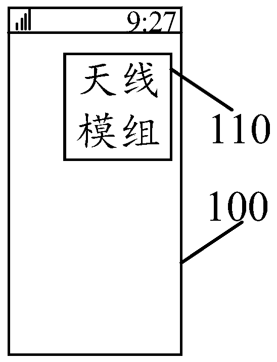
[0043] Please refer to figure 1 , figure 1 It is a schematic diagram of a scenario in which an antenna module is set in a terminal according to an exemplary embodiment of the present application. Such as figure 1 As shown, the terminal 100 may be in the form of a handheld mobile terminal 110, such as a mobile phone, a wearable device, or other portable electronic device that can be carried with you. Alternatively, the terminal 100 may also be an electronic device such as a tablet computer, an e-book reader, or a notebook computer. It should be noted that the antenna module used by the terminal 100 may be a MIMO antenna module.
[0044] In the embodiments of the present application, the MIMO antenna technology refers to a technology in which the transmitting end and the receiving end of the terminal 100 perform spatial diversity through multiple transmitting antennas and multiple receiving antennas, respectively. With the continuous upgrading of various components in the terminal 100, the form of the antenna module may also adopt different forms. In a possible implementation manner, the form of the antenna module in the terminal 100 may include a monopole (English: monopole) antenna form, a planar inverted F antenna form, an inverted F antenna form, and so on. Based on the application of the inverted-F antenna, optionally, the first antenna and the second antenna included in the antenna module 110 in the present application are inverted-F antennas, and both the first antenna and the second antenna are a type of end-coupled feeding antenna. In the embodiment of the present application, the first antenna includes a first free end and a first ground end. The second antenna includes a second free end and a second ground end.
[0045] In a possible manner, as the space requirements of the terminal 100 increase in design, the space occupied by the antenna module built in the terminal 100 is also becoming increasingly tight. In one design method, due to the increase in the space occupied by the camera assembly in the terminal 100, the distance between the antennas in the antenna module is getting closer and closer, and the antennas will be closer when the distance is closer. Produce a higher degree of coupling, thereby reducing the radiation efficiency of the antenna module. Optionally, when the antenna module 110 in the terminal 100 works in the Sub-6 GHz frequency band, the coupling degree of each antenna in the antenna module is relatively high.
[0046] In order to solve the above technical problem, an embodiment of the present application provides an antenna module. The antenna module can reduce the coupling degree between the respective feed ports of each antenna when the terminal uses the MIMO antenna to transmit signals, thereby improving the radiation efficiency of the antenna.
[0047] Please refer to figure 2 , figure 2 It is a schematic structural diagram of an antenna module provided by an exemplary embodiment of the present application. The antenna module can be applied to figure 1 In the terminal 100 in the application scenario shown. Such as figure 2 As shown, the antenna module 200 includes a first feeder 210, a second feeder 220, a 180° hybrid network 230, a first antenna 240, and a second antenna 250. Among them, the 180° hybrid network 230 is used to improve the isolation between the first antenna 240 and the second antenna 250.
[0048] The first antenna 240 includes a first free end 241 and a first ground end 242. The first antenna 240 is fed through the first free end 241.
[0049] The second antenna 250 includes a second free end 251 and a second ground end 252. Wherein, the second free end 251 and the first free end 241 are arranged oppositely to form a target gap. The second antenna 250 is fed through the second free end 251.
[0050] In the 180° hybrid network 230, the hybrid network includes a first port 231, a second port 232, a third port 233, and a fourth port 234. Among them, the first power feeder 210 is connected to the first port 231, the second power feeder 220 is connected to the fourth port 234, the first free end 241 is connected to the second port 232, and the second free end 251 is connected to the third port 233. Connected. The first port and the fourth port are mutually isolated ports.
[0051] In the 180° hybrid network 230, the first port 231 and the fourth port 234 are isolated ports from each other. When the first port 231 is in a working state, the fourth port 234 is in a non-working state. When the fourth port 234 is in a working state, the first port 231 is in a non-working state.
[0052] Optionally, in the embodiment of the present application, the 180° hybrid network may be a distributed device or a lumped element, which is not limited in the embodiment of the present application.
[0053] For the radio frequency signal transmission process, the radio frequency signal can enter the 180° hybrid network 230 through the first feeder 210 or the second feeder 220, undergo processing by the 180° hybrid network, and then pass through the first antenna 240 and/or the second antenna 240. The antenna 250 emits.
[0054] For the receiving process of the radio frequency signal, the radio frequency signal may be received by the first antenna 240 and/or the second antenna 250, processed by the 180° hybrid network, and then enter the first feeder 210 or the second feeder 220.
[0055] In the embodiment of the present application, the first antenna 240 and the second antenna 250 are both coupled antennas. Optionally, the feed point of the coupled antenna is located at the end of the antenna. Therefore, the coupled antenna is also called an end-fed inverted F antenna or a 1/8-wavelength antenna, which is not limited in the embodiment of the present application. It should be noted that the antenna end may be a quarter of the area from the antenna head to the antenna tail.
[0056] Optionally, the first antenna or the second antenna can transmit signals in any frequency band. The 180° hybrid network 230 can provide the function of suppressing the signal from the first feeder, and suppress the signal from flowing into the second feeder, thereby causing the coupling between the two feeder ports and improving the isolation between the antennas .
[0057] In summary, the antenna module provided by the embodiments of the present application includes: a first feeder, a second feeder, a 180° hybrid network, a first antenna, and a second antenna. Both the first antenna and the second antenna are coupled antennas. Among them, the 180° hybrid network includes a first port, a second port, a third port, and a fourth port; the first port of the 180° hybrid network is connected to the first feeder, and the second port is connected to the first free end. The three ports are connected to the second free end, and the fourth port is connected to the second feeder. When the first power feeder or the second power feeder sends the first radio frequency signal, the ports connected to the first power feeder or the second power feeder are isolated through a 180° hybrid network, so that the two power feeders are each The emitted signals will not affect each other, thereby improving the isolation between the antennas in the antenna module and improving the radiation efficiency of the antenna module.
[0058] In a possible implementation manner provided by the embodiment of the present application, the antenna module further includes a matching circuit, and the matching circuit can be connected to the 180° hybrid network according to actual requirements. As a possible implementation, take four matching circuits connected to the four ports of a 180° hybrid network as an example. figure 2 The antenna module shown is introduced.
[0059] Please refer to image 3 , image 3 It is a schematic structural diagram of an antenna module provided by an embodiment of the present application. in image 3 In, the antenna module can be applied in figure 1 In the terminal shown, the antenna module 300 includes a first feeder 310, a second feeder 320, a 180° hybrid network 330, a first antenna 340, a second antenna 350, a first matching circuit 360, and a second The matching circuit 370, the third matching circuit 380, and the fourth matching circuit 390. The first antenna 340 includes a first free end 341, and the second antenna 350 includes a second free end 351.
[0060] For the connection of the 180° hybrid network 330, the 180° hybrid network 330 includes a first port 331, a second port 332, a third port 333, and a fourth port 334. The first power feeder 310 is connected to the input terminal of the first matching circuit 360, and the output terminal of the first matching circuit 360 is connected to the first port 331; the second power feeder 320 is connected to the input terminal of the fourth matching circuit 390. The output end of the four matching circuit 390 is connected to the fourth port 334; the second port 332 is connected to the input end of the second matching circuit 370, the output end of the second matching circuit 370 is connected to the first free end 341; the third port 333 is connected to The input end of the third matching circuit 380 is connected, and the output end of the third matching circuit 380 is connected to the second free end 351.
[0061] Optionally, each matching circuit is used to achieve matching impedance between the two connected devices. For example, for the first matching circuit 360, the function of the matching circuit may be to achieve impedance matching between the output terminal of the first power feeder 310 and the first port 331. For the fourth matching circuit 390, the function of the fourth matching circuit 390 may be to achieve impedance matching between the output terminal of the second power feeder 320 and the fourth port 334. For the second matching circuit 370, the function of the second matching circuit 370 may be to achieve impedance matching between the second port 332 and the first antenna 340. For the third matching circuit 380, the function of the third matching circuit 380 may be to achieve impedance matching between the third port 333 and the second antenna 350.
[0062] Optionally, the matching circuit in the embodiment of the present application includes at least one capacitive device and/or inductance device. The matching circuit may be any one of the first matching circuit, the second matching circuit, the third matching circuit, or the fourth matching circuit. In other words, any one of the aforementioned matching circuits can include at least one capacitive device or one inductive device.
[0063] In a possible implementation manner, the electrical components included in the first matching circuit 360 are the same as those included in the fourth matching circuit 390, and the components of the second matching circuit 370 and the third matching circuit 380 are the same.
[0064] Optionally, in the embodiment of the present application, the matching circuit may further include at least one switch, and the switch is used to change the impedance in the matching circuit to achieve impedance conversion, thereby changing the frequency when the connected antenna sends a signal. . Please refer to Figure 4 , In the matching circuit 400, a first branch 410 and a second branch 420 are included. Wherein, the first branch 410 includes a first capacitor 411, a first inductor 412, a first switch 413, and a second switch 414. The second branch 420 includes a second capacitor 421, a second inductor 422 and a third switch 423. In the embodiment of the present application, the matching circuit 400 realizes the change of its own impedance by changing the on and off states of each switch.
[0065] In a possible implementation manner, the capacitive device or the inductance device in the above matching circuit can also be a tunable capacitive device or a tunable inductance device, and the matching circuit can also change its own by adjusting the tunable capacitive device or the tunable inductance device. impedance. The embodiments of the present application do not limit this.
[0066] Optional, Figure 4 The form of the matching circuit shown is only one possible way. In practical applications, those skilled in the art can adjust capacitive devices, inductance devices and switches according to the actual requirements of the antenna assembly to form a corresponding matching circuit.
[0067] Please refer to Figure 5 , Which is a schematic circuit diagram of an antenna module shown in an embodiment of the present application. Such as Figure 5 As shown, it includes a first feeder 510, a second feeder 520, a 180° hybrid network 530, a first antenna 540, a second antenna 550, a first matching circuit 560, a second matching circuit 570, and a third The matching circuit 580 and the fourth matching circuit 590.
[0068] The 180° hybrid network 530 includes a first port 531, a second port 532, a third port 533, and a fourth port 534.
[0069] in Figure 5 Here, the first matching circuit 560 includes a first capacitor 561 and a first inductor 562. Wherein, the first end of the first capacitor 561 is connected to the first power feeding portion 510, and the second end of the first capacitor 561 is connected to the first end of the first inductor 562, and is connected to the first port 531. The second terminal of the first inductor 562 is grounded.
[0070] The second matching circuit 570 includes a second inductor 571 and a second capacitor 572, and the first end of the second inductor 571 is connected to the second port 532. The second end of the second inductor 571 is connected to the first end of the second capacitor 572 and is connected to the first antenna 540. The second terminal of the second capacitor 572 is grounded.
[0071] The third matching circuit 580 includes a third inductor 581 and a third capacitor 582, and the first end of the third inductor 581 is connected to the third port 533. The second end of the third inductor 581 is connected to the first end of the third capacitor 582 and is connected to the second antenna 550. The second end of the third capacitor 582 is grounded.
[0072] The fourth matching circuit 590 includes a fourth capacitor 591 and a fifth capacitor 592, and the first end of the fourth capacitor 591 is connected to the second feeder 520. The second end of the fourth capacitor 592 is connected to the first end of the fifth capacitor 592 and is connected to the fourth port 534. The second terminal of the fifth capacitor 592 is grounded.
[0073] It should be noted that the first matching circuit achieves impedance matching between the first power feeder and the 180° hybrid network through the cooperation of the inductance device and the capacitive device. The fourth matching circuit realizes impedance matching between the second power feeder and the 180° hybrid network through capacitive devices. The second matching circuit realizes impedance matching between the 180° hybrid network and the first antenna through the cooperation of the inductance device and the capacitive device. The third matching circuit realizes impedance matching between the 180° hybrid network and the second antenna through the cooperation of the inductance device and the capacitive device.
[0074] In the embodiments of the present application, the structure of the matching circuit described above is only exemplary, and does not limit the circuit composition that can achieve the design requirements of impedance matching. The designer can increase or decrease the number of capacitive devices and/or the number of inductance devices and change the connection mode of the matching circuit according to actual requirements, so as to achieve the design requirements of impedance matching in the antenna assembly in the embodiment of the present application.
[0075] Optionally, to Figure 5 For example, the self-coupling degree of the 180° hybrid network in 3dB is 3dB, Figure 5 The values of the capacitive device and the inductive device in can be as follows: the first capacitance 561 is 0.35pF (picofarad), the first inductance 562 is 2.3nH (nanohenry), the second inductance 571 is 3nH, and the second capacitance 572 is 0.3pF The third inductor 581 is 3 nH, the third capacitor 582 is 0.3 pF, the fourth capacitor 591 is 1 pF, and the fifth capacitor 592 is 0.55 pF.
[0076] Optionally, the 180° hybrid network provided in the embodiment of the present application may work in out-of-phase output or in-phase output. When the signal is input through the first port of the 180° hybrid network, the signal will be evenly divided into two in-phase components at the second and third ports, and then transmitted through the antennas connected to the second and third ports. The fourth port will be isolated at this time. When the signal is input through the fourth port of the 180° hybrid network, the signal will be evenly divided into two out-of-phase components at the second and third ports (that is, the phase difference between the two out-of-phase components is 180° ), and then radiate out through the antennas connected to the second port and the third port. At this time, the first port will be isolated. It can be seen from the above working process that the 180° hybrid network can suppress the signal between the first power feeder and the second power feeder, and improve the isolation between the first power feeder and the second power feeder. Optionally, the scattering matrix S of the 180° hybrid network with a coupling degree of 3 dB involved in this application can be expressed in the following form:
[0077]
[0078] Among them, -j is an imaginary number.
[0079] in Figure 5 In the circuit structure shown, the radio frequency signal may enter the 180° hybrid network 530 through the first feeder 510 or the second feeder 520, and then be transmitted out through the first antenna 540 and the second antenna 550. Wherein, when the radio frequency signal is sent from the first power feeder 510, the first port 531 is a signal input port, the second port 532 and the third port 533 are signal output ports, and the fourth port 534 is an isolated port. At this time, the phase difference between the respective output signals of the second port 532 and the third port 533 is 0°, that is, the scene is an in-phase output scene. In other words, when the radio frequency signal is sent from the first power feeder and is input from the first shorts 531 to the 180° hybrid network, the phase difference between the respective output signals of the second port 532 and the third port 533 is 0°.
[0080] In another possible implementation manner, when the radio frequency signal is sent from the second feeder 520, the fourth port 534 is a signal input port, the second port 532 and the third port 533 are signal output ports, and the first port 531 It is an isolated port. At this time, the phase difference between the respective output signals from the second port 532 and the third port 533 is 180°. In other words, when the radio frequency signal is sent from the output terminal of the second feeder 520 and is input from the fourth port 534 into the 180° hybrid network, the phase difference between the respective output signals of the second port 532 and the third port 533 Is 180°. Optionally, in the embodiment of the present application figure 2 The 180° hybrid network shown can also work in a similar manner, and will not be repeated here.
[0081] As a possible implementation, the 180° hybrid network can be any of a wake-up hybrid network, a gradually changing matching line network, a gradually changing coupled line network, a hybrid waveguide junction network, or a magic T network. Please refer to Image 6 , Which is a schematic structural diagram of a ring hybrid network provided by an embodiment of the present application. Such as Image 6 As shown, the ring hybrid network 600 includes a first port 610, a second port 620, a third port 630, and a fourth port 340. When a signal is input from the first port 610 to the ring hybrid network 600, the ring hybrid network 600 The signal can be evenly divided into two in-phase components, and the second port 620 and the third port 630 are output in the same amplitude and in the same phase. At this time, the fourth port 640 is isolated, that is, there is no output or input. After the radio frequency signal is input into the ring hybrid network 600 from the fourth port 640, the ring hybrid network 600 can evenly divide the signal into two inverted components, which are output by the second port 620 and the third port 630 in equal amplitude. At this time, the first port 610 is isolated, that is, there is no output or input.
[0082] Please refer to Figure 7 , Figure 7 It is a schematic structural diagram of a gradual matching line network provided by an embodiment of the present application. Such as Figure 7 As shown, the gradual matching line network 700 includes a first port 710, a second port 720, a third port 730, and a fourth port 740. Among them, the working mode of the gradient matching line network 700 can refer to the above Image 6 The described working method will not be repeated here. Optionally, the gradually changing matching line network may also be called a gradually changing coupling line network.
[0083] Please refer to Figure 8 , Figure 8 It is a schematic structural diagram of a hybrid waveguide junction network provided by an embodiment of the present application. Such as Figure 8 As shown, the hybrid waveguide junction network 800 includes a first port 810, a second port 820, a third port 830, and a fourth port 840. Among them, the working mode of the hybrid waveguide junction network 800 can also refer to the above Image 6 The working method shown is not repeated here. Optionally, the hybrid waveguide junction network can also be referred to as a magic T network.
[0084] In a possible implementation manner, the first antenna and the second antenna included in the antenna module provided in this embodiment of the application are both coupled antennas. Optionally, when the antenna module is integrated in the terminal, the transmission of the first antenna and the second antenna are opposite, and the first antenna and the second antenna can be designed on the same ground plate and input through their respective feed ports The radio frequency signal that needs to be sent.
[0085] Please refer to Picture 9 , Picture 9 It is a schematic structural diagram of an antenna module designed in an embodiment of the present application. Such as Picture 9 As shown, the antenna module 900 includes a first feeder 910, a second feeder 920, a 180° hybrid network 930, a first antenna 940, a second antenna 950, a matching circuit 960 and a PCB (English: Printed Circuit Boards, Chinese: Printed Circuit Board) 970.
[0086] in Picture 9 In the specific internal connection mode of the antenna module shown, the first feeder 910 can be connected to the fourth port of the 180° hybrid network 930 through the matching circuit 960, and the third port of the 180° hybrid network 930 can be connected through the matching circuit. 960 is connected to the first antenna 940, and the fourth port of the 180° hybrid network 930 can be connected to the second antenna 950 through the matching circuit 960. Optionally, the first antenna 940 includes a first antenna feed point, and the second antenna 950 may include a second antenna feed point. The fourth port of the 180° hybrid network can be connected to the second antenna feed point of the second antenna 950 through the matching circuit 960. The first antenna includes a first free end 941, and the second antenna includes a second free end 951. Wherein, the gap between the first free end 941 and the second free end 951 may be a target gap.
[0087] The radio frequency integrated circuit (RFIC) on the PCB can input radio frequency signals into the 180° hybrid network 930 through the first feeder 910 or the second feeder 920, and then pass the first antenna 940 and the second antenna 940 The transmitting end of the antenna 950 radiates out, and the working principle of the 180° hybrid network 930 can refer to the above content, which will not be repeated here.
[0088] Optional, Picture 9 The antenna module shown can work in the FR1 (Frequency range 1, frequency range 1) frequency band and the FR2 (Frequency range 2, frequency range 2) frequency band in the 5G frequency band. Among them, the FR2 frequency band is also called the sub-6GHz frequency band. That is, the antenna module can transmit radio frequency signals in the Sub-6GHz frequency band. Please refer to Picture 10 , Which shows that an exemplary embodiment of this application involves Picture 9 A schematic diagram of the current distribution when the first antenna and the second antenna are excited in the same phase. Such as Picture 10 As shown, it includes a first antenna 1010, a second antenna 1020, a first antenna feed point 1011, and a second antenna feed point 1021. When Picture 9 When the shown antenna module sends out a 3.6GHz radio frequency signal through the first feeder, the antenna module can excite such as Picture 10 Current distribution shown.
[0089] Please refer to Picture 11 , Which shows that an exemplary embodiment of this application involves Picture 9 A schematic diagram of the current distribution when the first antenna and the second antenna are differently excited. Such as Picture 11 As shown, it contains a first antenna 1110, a second antenna 1120, a first antenna feed point 1111, and a second antenna feed point 1121. When Picture 9 When the antenna module shown sends out a 3.6GHz radio frequency signal through the second feeder, the antenna module can be excited such as Picture 11 Current distribution shown.
[0090] Please refer to Picture 12 , Which shows that an exemplary embodiment of this application involves Picture 9 The reflection parameter change graph of the first antenna and the second antenna. Such as Picture 12 As shown, it contains the reflection parameter curve 1210 between the first antenna and the first antenna, the reflection parameter curve 1230 between the first antenna and the second antenna, and the reflection parameter curve 1220 between the second antenna and the second antenna. , The first sampling point is 1250. Among them, due to the reflection parameter curve 1240 between the second antenna and the first antenna. by Picture 12 From the first sampling point 1250 in, it can be known that when the first antenna transmits a signal with a frequency of 3.6 GHz, the isolation between the first antenna and the second antenna is -23.965 dB. It should be noted, Picture 12 The unit of the horizontal axis is GHz, and the unit of the vertical axis is dB.
[0091] Please refer to Figure 13 , Figure 13 Is an exemplary embodiment of this application relates to Picture 9 The reflection parameter change curve diagram of the first antenna and the second antenna included in the antenna module of the 180° hybrid network is removed in the. Such as Figure 13 As shown, it contains the reflection parameter curve 1330 between the first antenna and the first antenna, the reflection parameter curve 1310 between the first antenna and the second antenna, and the reflection parameter curve 1320 between the second antenna and the second antenna. , The first sampling point 1340. Among them, since the reflection parameter curve between the second antenna and the first antenna coincides with the reflection parameter curve 1310, Figure 13 Not marked in. among them, Figure 13 Is the above Figure 8 After removing the 180° hybrid network in, the result curve of the reflection parameters of the first antenna and the second antenna is determined by Figure 13 From the first sampling point 1340 in, it can be known that when the first antenna transmits a signal with a frequency of 3.6 GHz, the isolation between the first antenna and the second antenna is -2.6515 dB. Obviously, from Picture 12 with Figure 13 It can be seen from the comparison that by adding a 180° hybrid network, the isolation between the first antenna and the second antenna can be improved. It should be noted, Figure 13 The unit of the horizontal axis is GHz, and the unit of the vertical axis is dB.
[0092] Please refer to Figure 14 , Figure 14 Is an exemplary embodiment of this application relates to Picture 9 The system efficiency change graph of the first antenna and the second antenna. Such as Figure 14 As shown, the system efficiency curve 1420 of the first antenna, the system efficiency curve 1410 of the second antenna, and the first sampling point 1430 are included. by Figure 14 From the first sampling point 1430 in, it can be known that when the first antenna transmits a signal with a frequency of 3.6 GHz, the system efficiency of the first antenna is -0.028843 dB. At the same time, when the second antenna transmits a signal with a frequency of 3.6 GHz, the system efficiency of the second antenna is also -0.028843 dB. It should be noted, Figure 14 The unit of the horizontal axis is GHz, and the unit of the vertical axis is dB.
[0093] Please refer to Figure 15 , Figure 15 Is an exemplary embodiment of this application relates to Picture 9 The system efficiency change graph of the first antenna and the second antenna included in the antenna module of the 180° hybrid network is removed in the middle. Such as Figure 15 As shown, the system efficiency curve 1510 of the first antenna, the system efficiency curve 1520 of the second antenna, the first sampling point 1511 and the second sampling point 1521 are included. among them, Figure 15 Is the above Picture 9 After removing the 180° hybrid network in the system, the result curve of the system efficiency detection of the first antenna and the second antenna is determined by Figure 15 From the first sampling point 1511 in, it can be known that when the first antenna transmits a signal with a frequency of 3.6 GHz, the system efficiency of the first antenna is -3.4707 dB. by Figure 15 From the second sampling point 1521 in, it can be known that when the second antenna transmits a signal at a frequency of 3.6 GHz, the system efficiency of the second antenna is -3.5385 dB. Obviously, from Figure 14 with Figure 15 It can be seen from the comparison that by adding a 180° hybrid network, the system efficiency of the first antenna and the second antenna can also be improved. It should be noted, Figure 15 The unit of the horizontal axis is GHz, and the unit of the vertical axis is dB.
[0094] Please refer to Figure 16 , Figure 16 It is a schematic diagram of an ECC variation curve involved in an exemplary embodiment of the present application, such as Figure 16 As shown, it contains a first curve 1610, a second curve 1620, a first sampling point 1611, and a second sampling point 1621. Among them, the first curve 1610 is the above Picture 9 The curve of the ECC between the first antenna and the second antenna in the second curve 1620 is the above Picture 9 After removing the 180° hybrid network, the ECC curve between the first antenna and the second antenna included in the antenna module is removed. by Figure 16 The first sampling point 1610 in, we can see that when the antenna module transmits a signal at a frequency of 3.6 GHz, the ECC between the first antenna and the second antenna is 0.0020521, which is determined by Figure 16 The second sampling point 1604 in, we can see that when the antenna module without the 180° directional coupler transmits a signal at a frequency of 3.6 GHz, the ECC between the first antenna and the second antenna is 3.9889*e -05 It can be seen from the first sampling point 1611 and the second sampling point 1621 that the use of a 180° hybrid network can reduce the ECC between the first antenna and the second antenna, thereby reducing the isolation between the antennas. In addition, by Figure 16 It can also be seen from the first curve 1601 and the second curve 1602 in the antenna module that the ECC of the first antenna and the second antenna in the antenna module using the 180° hybrid network is also lower than that of the antenna module in each frequency band. The former ECC.
[0095] In summary, since the antenna module includes a first feeder, a second feeder, a 180° hybrid network, a first antenna, and a second antenna, the 180° hybrid network includes a first port, and a second antenna. Two ports, a third port and a fourth port, the 180° hybrid network is used to improve the isolation between the first antenna and the second antenna; the first feeder and the first port The second feeder is connected to the fourth port; the first antenna includes a first free end, the second port is connected to the first free end, and the first antenna feeds power at the first free end; The second antenna includes a second free end, the second free end is opposite to the first free end and forms a target gap, the third port is connected to the second free end, and the second antenna feeds power at the second free end. In the antenna module of this structure, when the first feeder or the second feeder emits the target radio frequency signal, the antenna module can isolate the signals emitted by the two feeders through a 180° hybrid network, thereby improving The isolation between the first power feeder and the second power feeder reduces the ECC (Envelope Correlation Coefficient) between the first antenna and the second antenna, and improves the radiation efficiency of the antenna module.
[0096] The serial numbers of the foregoing embodiments of the present application are only for description, and do not represent the advantages and disadvantages of the embodiments.
[0097] Those of ordinary skill in the art can understand that all or part of the steps in the foregoing embodiments can be implemented by hardware, or by a program instructing related hardware to be completed. The program can be stored in a computer-readable storage medium. The storage medium mentioned can be a read-only memory, a magnetic disk or an optical disk, etc.
[0098] The above are only exemplary embodiments that can be implemented in this application, and are not intended to limit the application. Any modification, equivalent replacement, improvement, etc. made within the spirit and principle of this application shall be included in Within the scope of protection of this application.
PUM


Description & Claims & Application Information
We can also present the details of the Description, Claims and Application information to help users get a comprehensive understanding of the technical details of the patent, such as background art, summary of invention, brief description of drawings, description of embodiments, and other original content. On the other hand, users can also determine the specific scope of protection of the technology through the list of claims; as well as understand the changes in the life cycle of the technology with the presentation of the patent timeline. Login to view more.