Rapid braking control system and control method for three-phase switched reluctance motor

A reluctance motor, three-phase switch technology, used in control systems, AC motor control, electrical components, etc., can solve the problems of inability to achieve frequent braking, inability to meet use requirements, low braking efficiency, etc., and achieve high reliability. , High space utilization, and the effect of improving braking efficiency

Pending Publication Date: 2020-02-21
WOLONG ELECTRIC NANYANG EXPLOSION PROTECTION GRP CO LTD +1
View PDF0 Cites 5 Cited by
  • Summary
  • Abstract
  • Description
  • Claims
  • Application Information

AI Technical Summary

Problems solved by technology

[0003] Traditional switched reluctance motors and their transmission systems mostly use electromagnetic brakes for braking. This braking method not only requires the installation of electromagnetic braking equipment in the already narrow operating space, but also generates a lot of heat during the braking process. Additional heat dissipation equipment is installed for heat dissipation, and frequent braking cannot be achieved
More importantly, because the switched reluctance motor controller needs to stop working first during electromagnetic braking, after the electromagnetic brake stops, the switched reluctance motor controller will switch to the working state again. This process takes a long time to brake. and low braking efficiency
In the current situation of increasing requirements for frequent braking and fast designation, the braking method of the existing switched reluctance motor speed control system can no longer meet the needs of use
[0004] It is necessary to seek a braking method with high efficiency, short braking time, precise control of braking time, and frequent braking to solve the problem of fast, accurate and efficient braking of the switched reluctance motor speed control system

Method used


Image

  • Rapid braking control system and control method for three-phase switched reluctance motor
  • Rapid braking control system and control method for three-phase switched reluctance motor

Examples


Embodiment Construction

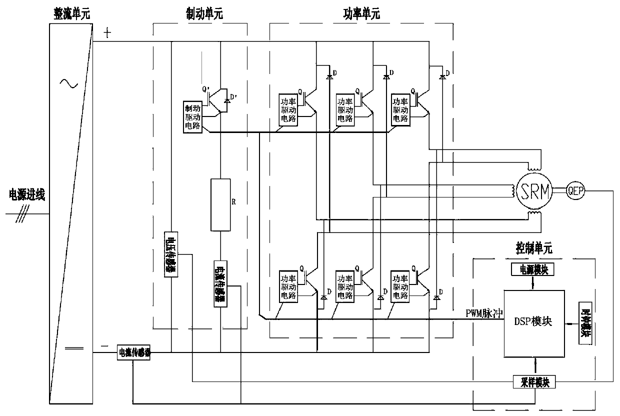
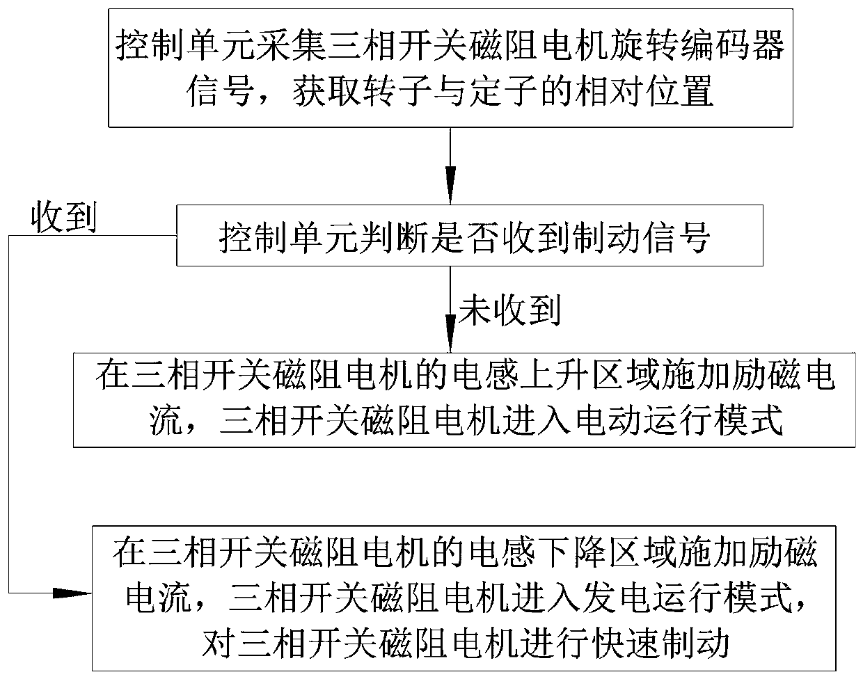
[0041] Such as figure 1 As shown, the present invention includes a fast braking control system and braking method for a three-phase switched reluctance motor.

[0042] The brake control system includes a rectifier unit, a power conversion unit, a control unit and a brake unit. The rectifier unit provides the power current required by the control system through the DC bus;

[0043] The rectifier unit is respectively connected to the three-phase coils of the three-phase switched reluctance motor through the power conversion unit;

[0044] The power conversion unit includes three asymmetrical half-bridge power circuits, and the three-way asymmetrical half-bridge power circuits are connected to the three-phase coils of the three-phase switched reluctance motor in one-to-one correspondence;

[0045] The braking unit includes a braking IGBT module and a braking resistor. The braking IGBT module is connected in series with the braking resistor and connected to both ends of the rectifi...


PUM


Abstract

The invention discloses a rapid braking control system and method for a three-phase switched reluctance motor. The system comprises a rectification unit, a power conversion unit, a control unit and abrake unit. The brake unit composed of a brake IGBT module and a brake resistor is adopted, and a braking current closed loop is realized in a braking process. Rapid braking and frequent braking of the switched reluctance motor are realized. In the braking process, closed-loop control over the rotating speed and the current is achieved, and rotating speed and current signals are synchronously received. The relation among the braking time, the braking current and the shafting rotating speed is synchronously adjusted through a DSP module. Rapid braking is achieved, and at the same time shaftingrotating can be stopped within a designated braking time. The precision is high. The reliability is high. The flexibility is high.

Description

technical field [0001] The invention relates to the technical field of switched reluctance motor drive systems, in particular to a three-phase switched reluctance motor rapid braking control system and control method. Background technique [0002] With the rapid development of the motor industry, due to the advantages of wide speed range, high efficiency, long life and high investment benefits of the speed control system, the advantages of switched reluctance motors have become more and more significant, and have been widely used in metallurgy, machinery, petroleum, Port terminals, mines, aerospace and other fields. In many application fields, such as machinery, tunnel drilling and other industries, the motor needs to rotate forward and reverse frequently. Therefore, the length of the braking time directly determines the level of work efficiency, which also puts forward the braking time of the switched reluctance motor. more stringent requirements. [0003] Traditional swi...

Claims


Application Information

Patent Timeline
Patent Type & Authority Applications(China)
IPC IPC(8): H02P6/24H02P6/16H02P27/08H02P25/18
CPCH02P6/16H02P6/24H02P25/18H02P27/08
Inventor 刘平顺吴宣东张浩赵跃东张道洋范宏伟刘建波周良逵振雨高乔张虎付晓苑旭东
Owner WOLONG ELECTRIC NANYANG EXPLOSION PROTECTION GRP CO LTD
Why Eureka
Try Eureka