Roller assembly and side approaching machine

A technology of rollers and components, which is applied in the field of the structure of side-by-side machines, can solve the problems such as the rollers cannot be disassembled, and achieve the effect of avoiding production accidents and avoiding detachment.

Pending Publication Date: 2020-02-25
XINHAI IND BELTING
View PDF0 Cites 1 Cited by
  • Summary
  • Abstract
  • Description
  • Claims
  • Application Information

AI Technical Summary

Problems solved by technology

[0003] In order to overcome the deficiencies of the prior art, the object of the present invention is to provide a roller assembly, which s

Method used


Image

  • Roller assembly and side approaching machine
  • Roller assembly and side approaching machine
  • Roller assembly and side approaching machine

Examples


Example Embodiment

[0027] In the following, the present invention will be further described in conjunction with the drawings and specific implementations. It should be noted that, provided that there is no conflict, the following embodiments or technical features can be combined to form new embodiments. .

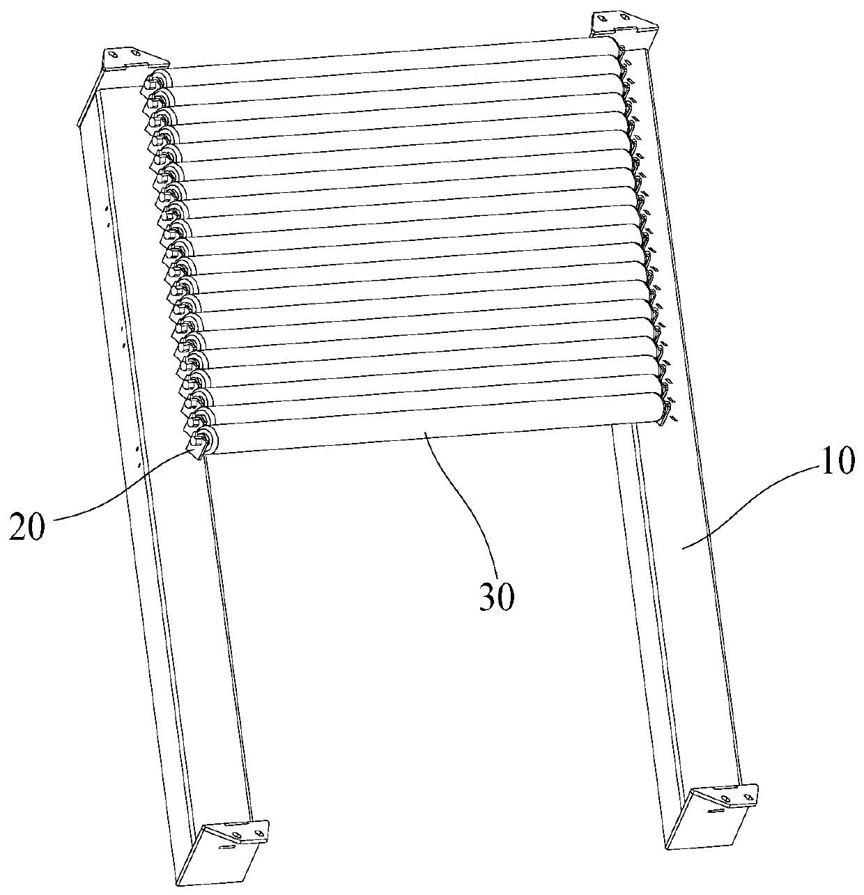
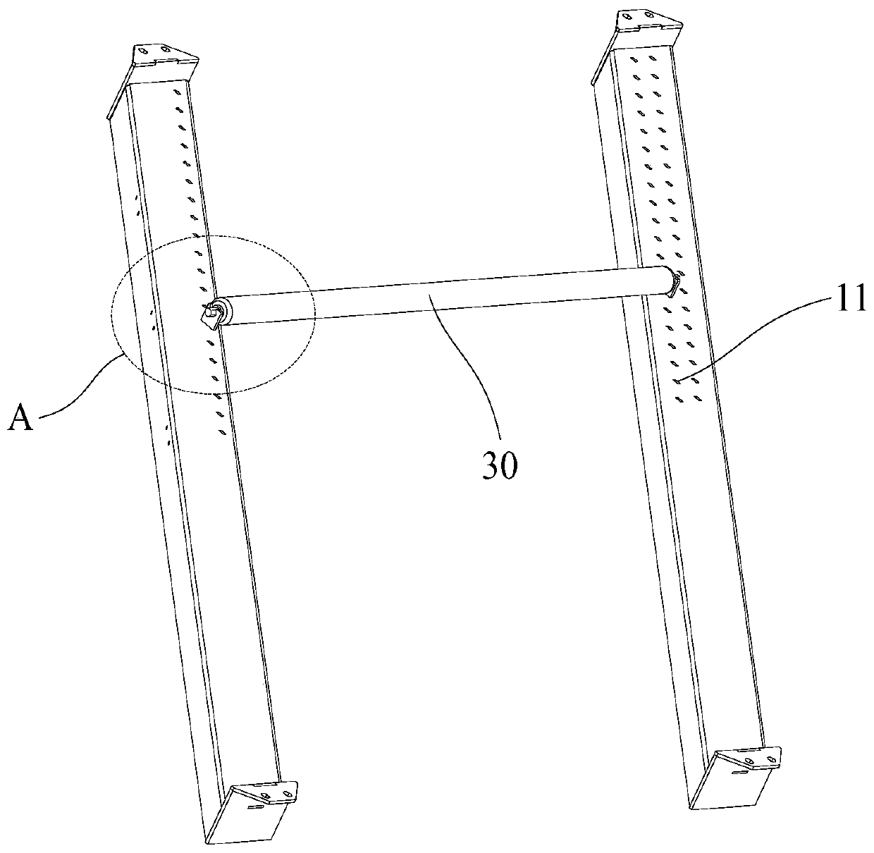
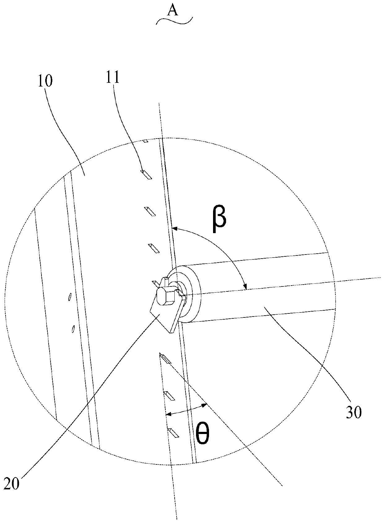
[0028] See Figure 1 to Figure 4 The embodiment of the present invention provides a roller assembly 1. The roller assembly 1 includes two support rods 10, a number of clamping seats 20, and a number of rollers 30. Each support rod 10 is provided with a number of The card seat 20 is provided with a card slot 21 on the side of the card seat 20 away from the support rod 10. The roller 30 can be detachably installed in the card slot 21 to facilitate later maintenance of the side machine. The roller 30 can be removed from the card slot 21 at any time Come down.

[0029] See further Figure 5 to Figure 7 The card slot 21 includes two parallel groove side surfaces 211 and a groove bottom surface 212 co...


PUM


Abstract

The invention discloses a roller assembly and a side approaching machine. The roller assembly comprise two supporting rods, a plurality of clamping seats and a plurality of rollers, wherein the plurality of clamping seats are arranged at the top surface of each supporting rod at intervals, and clamping grooves are formed in the sides, far away from the supporting rods, of the clamping seats; eachclamping groove comprises two parallel groove side faces and a groove bottom face connected with the two groove side faces, and the normal directions between the groove side faces and the groove bottom face are arranged at included angles alpha; and each rollers comprises a supporting shaft and a rotating cylinders arranged outside the supporting shaft in a sleeving mode, one end of the supportingshaft is arranged on the clamping seat on one supporting rod in a clamped mode, and the other end of the supporting shaft is arranged on the clamping seat on the other supporting rod in a clamped mode. According to the roller assembly and the side approaching machine, the clamping grooves are formed in the side, far away from the supporting rods, of the clamping seats, and the rollers are detachably arranged in the clamping grooves so that the rollers can be detached from the clamping grooves at any time during later maintenance; and meanwhile, the normal directions between the groove side faces and the groove bottom face are arranged at the included angles alpha, and the whole clamping grooves are inclined grooves which are obliquely arranged so that the rollers can be effectively prevented from being separated from the clamping grooves when the side approaching machine is operated, and production accidents are avoided.

Description

technical field [0001] The invention relates to the technical field of edge puller structures, in particular to a roller assembly and an edge puller. Background technique [0002] In the prior art, the rollers on the side puller and the installation strips are fixedly connected by locks and screws to prevent the rollers from detaching from the installation strips during the operation of the side puller, thereby causing production accidents. However, after such assembly, The rollers cannot be quickly disassembled from the mounting strips during later maintenance. Contents of the invention [0003] In order to overcome the deficiencies of the prior art, the purpose of the present invention is to provide a roller assembly, which solves the technical problem that the rollers of the existing edge puller cannot be quickly disassembled from the installation strip. [0004] The present invention adopts following technical scheme to realize: [0005] The present invention provide...

Claims


Application Information

Patent Timeline
IPC IPC(8): B65G13/00B65G13/11
CPCB65G13/00B65G13/11
Inventor 洪健荣
Owner XINHAI IND BELTING
Why Eureka
Try Eureka