
Novel cam divider

A cam divider, a new type of technology, applied to belts/chains/gears, mechanical equipment, transmission devices, etc., can solve the problems of inconvenient processing, production and use, easy wear and tear of indexing cams, and inability to adjust the position of output shafts. Simple, solve the effect of assembly production, convenient installation

Pending Publication Date: 2020-02-25
温州佳仕德精密科技有限公司
View PDF0 Cites 2 Cited by
  • Summary
  • Abstract
  • Description
  • Claims
  • Application Information

AI Technical Summary

Problems solved by technology

[0003] The position of the output shaft of the traditional cam divider cannot be adjusted. During assembly, not only the processing of the indexing cam and the machining size of the processing turret are required to be very precise, but also the position of the output turret needs to be fine-tuned several times to match the turret. For the quasi-indexing cam, the entire output shaft needs to be disassembled for each fine-tuning modification, and may even be completely scrapped; if the fine-tuning is not carried out, the two will not fit together, resulting in uneven force on the output turret, and the indexing cam is easy to wear , which brings inconvenience to processing, production and use

Method used


Image

  • Novel cam divider

Examples


Embodiment Construction

[0015] Hereinafter, the present invention will be described in more detail with reference to the accompanying drawings. This embodiment is only a description of the best implementation mode of the present invention, and does not limit the scope of the present invention in any way.

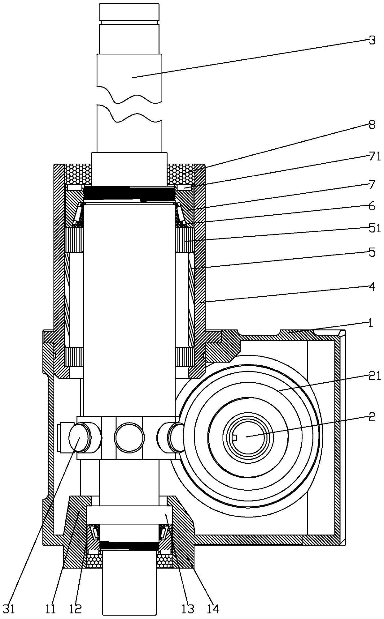
[0016] Such as figure 1 As shown, a new type of cam divider includes a housing 1, the housing 1 is provided with an input shaft 2 arranged horizontally and an output shaft 3 vertically arranged on one side of the input shaft 2, and the outer circumference of the input shaft 2 is sleeved with The indexing cam 21, the outer circumference of the output shaft 3 is sleeved with the output turret 31 matching the indexing cam 21, the auxiliary sleeve 4 is connected and fixed on one side of the housing 1, and the other side is provided with a fixed base 11, One end of the output shaft 3 passes through the auxiliary sleeve 4, and the other end passes through the fixed base 11. The auxiliary sleeve 4 is pro...


PUM


Abstract

The invention relates to a novel cam divider. The divider comprises a shell, wherein an input shaft transversely arrange and an output shaft vertically arranged on one side of the input shaft are arranged in the shell; an indexing cam is arranged on the periphery of the input shaft in a sleeving mode, and an output turret matched with the indexing cam is arranged on the periphery of the output shaft in a sleeving mode; one side of the shell is connected and fixed with an auxiliary sleeve, and the other side of the shell is provided with a fixing base; one end of the output shaft penetrates through the auxiliary sleeve, and the other end of the output shaft penetrates through the fixing base; a fixing sleeve is arranged in the auxiliary sleeve, and auxiliary rings are arranged on the two ends of the fixing sleeve; a placing groove is arranged at the end, far away from the auxiliary sleeve, of the fixing base, and a fixing ring is arranged in the groove; and adjusting pieces are arrangedat one sides of the auxiliary rings and one side of the fixing ring, oil seals are arranged on one sides of the adjusting pieces, and the adjusting pieces comprise taper bearings and clamping nuts matched with the taper bearings. According to the divider, the sleeves and the clamping nuts are matched with the output shaft, so that the up-down adjustment of the output turret is achieved, and the output turret can be better matched with the indexing cam.

Description

technical field [0001] The invention relates to the field of transmission equipment, in particular to a cam divider. Background technique [0002] Cam divider is also called cam divider and intermittent divider in engineering; it is a high-precision rotary device. When the input shaft rotates, the indexing cam rotates the output turret on the output shaft according to a given displacement curve. And the output turret rolls along the slope of the tapered support rib on the indexing cam at the same time. In the static state, the output turret itself does not rotate; the tapered support rib on the indexing cam is usually connected with two or three output turrets. Contact, so that the rotation of the input shaft can be evenly transmitted to the output shaft; [0003] The position of the output shaft of the traditional cam divider cannot be adjusted. During assembly, not only the processing of the indexing cam and the machining size of the processing turret are required to be v...

Claims


Application Information

Patent Timeline
Patent Type & Authority Applications(China)
IPC IPC(8): F16H27/04
CPCF16H27/04
Inventor 李旭春周仙战
Owner 温州佳仕德精密科技有限公司
Learn More