Locking mechanism and spindle structure

A locking mechanism and spindle technology, applied in the direction of gear cutting machine, mechanical equipment, metal processing mechanical parts, etc., can solve the problems of difficult operation, difficult to complete the operation by one person, etc., achieve simple and easy operation, easy maintenance work, avoid damage effect

Active Publication Date: 2020-02-28
HUNAN ZDCY (ZHONGDA CHUANG YUAN) CNC EQUIP CO LTD
View PDF8 Cites 0 Cited by
  • Summary
  • Abstract
  • Description
  • Claims
  • Application Information

AI Technical Summary

Problems solved by technology

[0002] CNC machine tools are generally equipped with a rotatable main shaft, and a detachable tool or workpiece is installed on the main shaft structure. Commonly used equipment for bevel gear processing, including gear grinding machines and milling machines, etc. During the workpiece, since the tool spindle or the workpiece spindle can rotate, the tool spindle or the workpiece spindle will follow the rotation during the process of loosening the corresponding threaded connection to disassemble the tool or the workpiece, so the operation is difficult
And although a wrench can form a fulcrum on the tool spindle or the workpiece spindle to relatively fix the tool spindle or the workpiece spindle, the operation is difficult, and it is difficult for a single person to complete the operation

Method used


Image

  • Locking mechanism and spindle structure
  • Locking mechanism and spindle structure
  • Locking mechanism and spindle structure

Examples


Embodiment Construction

[0026] Embodiments of the present invention are described in detail below, examples of which are shown in the drawings, wherein the same or similar reference numerals designate the same or similar elements or elements having the same or similar functions throughout. The embodiments described below by referring to the figures are exemplary only for explaining the present invention and should not be construed as limiting the present invention.

[0027] In the description of the present invention, it should be understood that the orientation descriptions, such as up, down, front, back, left, right, etc. indicated orientations or positional relationships are based on the orientations or positional relationships shown in the drawings, and are only In order to facilitate the description of the present invention and simplify the description, it does not indicate or imply that the device or element referred to must have a specific orientation, be constructed and operated in a specific ...


PUM


Abstract

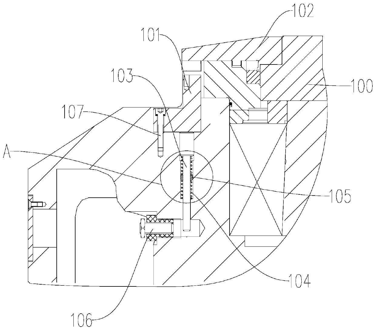
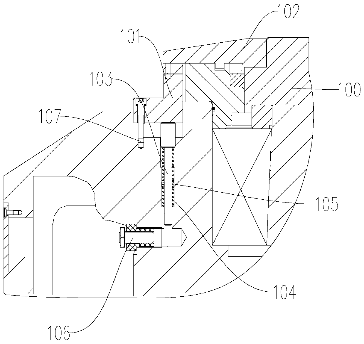
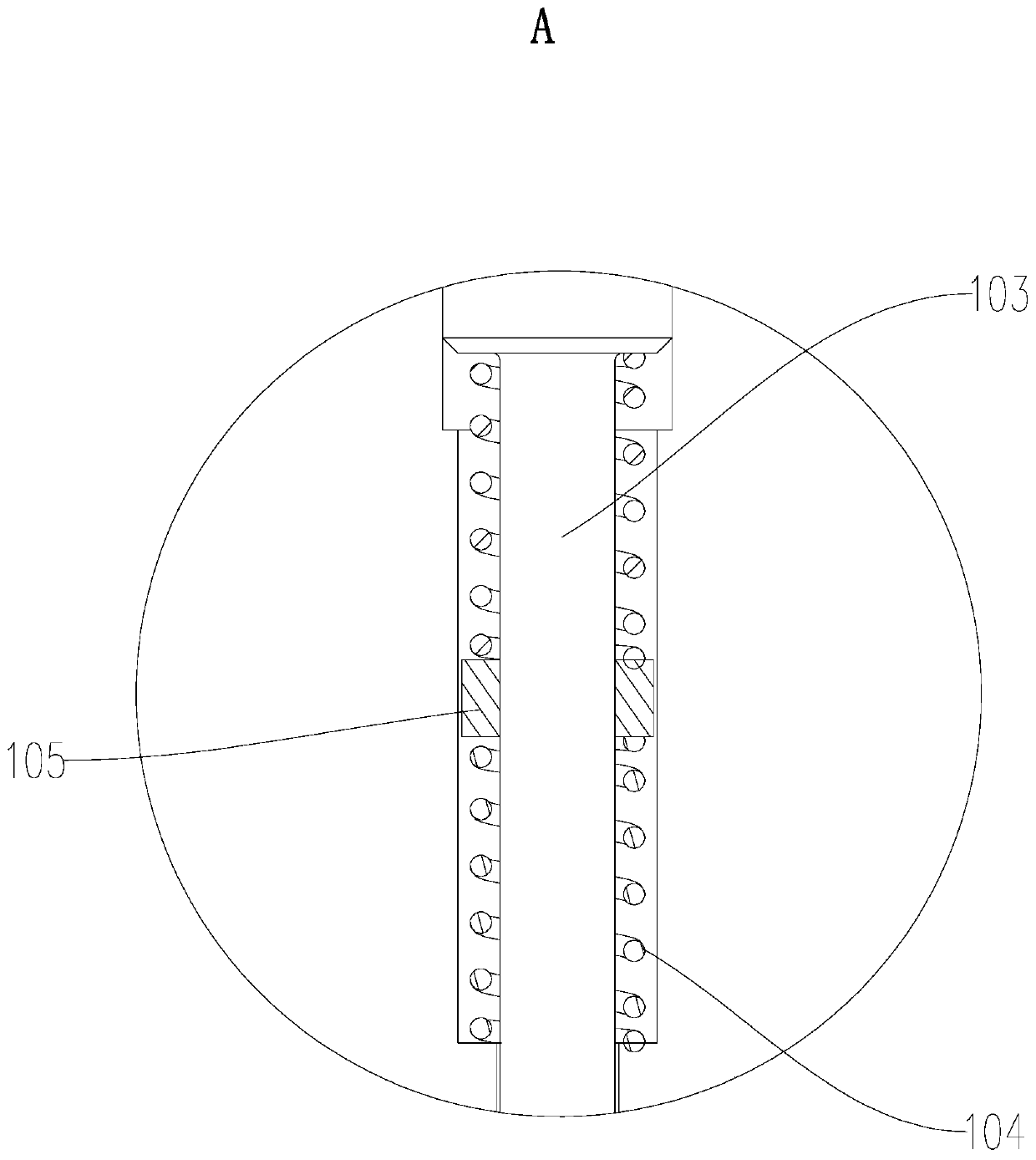
The invention discloses a locking mechanism and a spindle structure, and is used for solving the problem that a spindle is difficult to fix when a technician carries out repair and maintenance. The locking mechanism and the spindle structure are mainly applied to clamp a spindle when a cutter spindle or a workpiece spindle is disassembled and assembled or maintained; a regulating piece is regulated to make a locking device jack and hold the cutter spindle or the workpiece spindle under the action of a resetting device, and thus, the goal of fixing can be easily realized; the operation is simple and easy, and can be completed by one person; in addition, a detecting device is further arranged, and is used for detecting the position of the locking device; when the locking device is adjusted to a position where the detecting device can detect the locking device and obtain a feedback signal, loosening of the spindle is completed, and thereby, the normal operation of the spindle is not influenced; and the technician can check the detecting device to avoid that a main is started to run the spindle when the locking mechanism clamps the spindle, and thereby, damage to the spindle or the locking mechanism is avoided.

Description

technical field [0001] The invention belongs to the technical field of machine tools, and in particular relates to a locking mechanism and a spindle structure provided with the locking mechanism. Background technique [0002] CNC machine tools are generally equipped with a rotatable main shaft, and a detachable tool or workpiece is installed on the main shaft structure. Commonly used equipment for bevel gear processing, including gear grinding machines and milling machines, etc. During the workpiece, since the tool spindle or the workpiece spindle can rotate, the tool spindle or the workpiece spindle will follow the rotation during the process of unscrewing the corresponding threaded connection to disassemble the tool or the workpiece, so the operation is difficult. And although a wrench can be used to form a fulcrum on the tool spindle or the workpiece spindle to relatively fix the tool spindle or the workpiece spindle, the operation is difficult, and it is difficult for a ...

Claims


Application Information

Patent Timeline
Patent Type & Authority Applications(China)
IPC IPC(8): B23B19/02B23F23/00
CPCB23F23/00B23Q1/70
Inventor 张春晖李锡晗史伟
Owner HUNAN ZDCY (ZHONGDA CHUANG YUAN) CNC EQUIP CO LTD
Why Eureka
Try Eureka