
Method of controlling vehicle brake system

A technology for braking systems, wheel brakes, applied in control/regulating systems, brakes, vehicle components, etc., to solve problems such as application, excessive braking pressure, loss of directional control, etc.

Active Publication Date: 2020-02-28
ZF ACTIVE SAFETY US INC
View PDF11 Cites 4 Cited by
  • Summary
  • Abstract
  • Description
  • Claims
  • Application Information

AI Technical Summary

Problems solved by technology

Under these conditions, the driver can easily apply excessive brake pressure, causing one or more wheels to lock, which causes excessive slip between the wheels and the road surface
This locked wheel condition results in longer braking distances and the possibility of loss of directional control

Method used


Image

  • Method of controlling vehicle brake system
  • Method of controlling vehicle brake system
  • Method of controlling vehicle brake system

Examples


Embodiment Construction

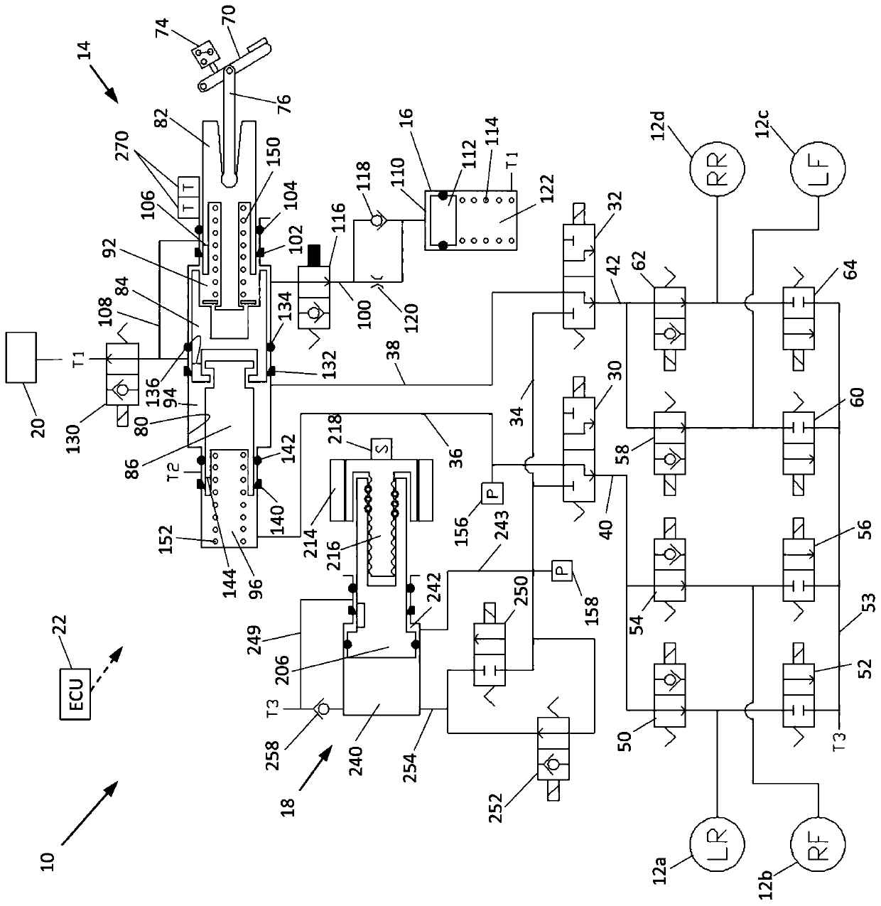
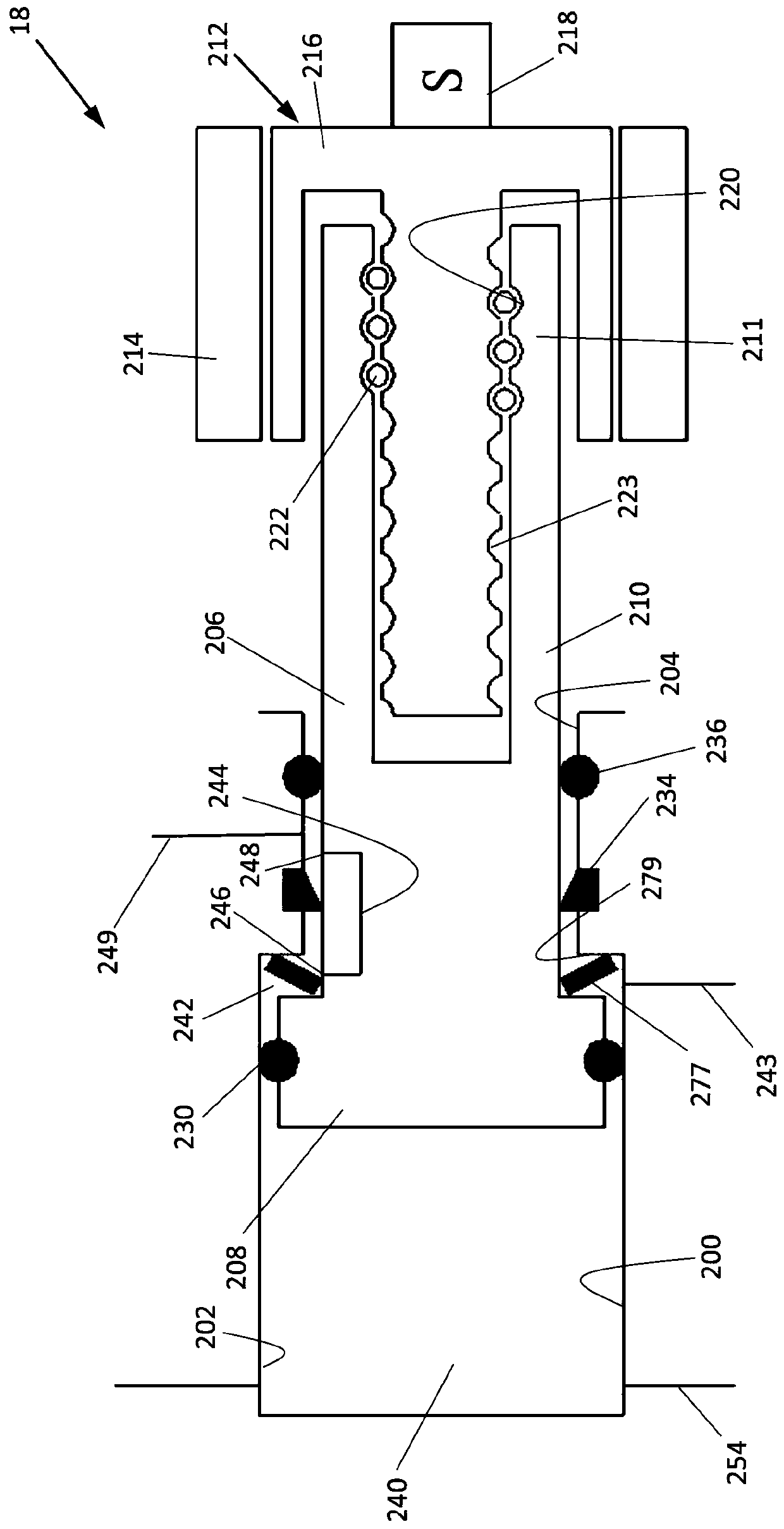
[0023] Referring now to the accompanying drawings, in figure 1 A first embodiment of a vehicle braking system, indicated generally at 10 , is schematically shown in FIG. The braking system 10 is a hydraulic braking system in which fluid pressure from a source is operated to apply braking pressure for the braking system 10 . Braking system 10 may be adapted for use in ground vehicles, such as motor vehicles with four wheels. Additionally, the braking system 10 may be provided with other braking functions, such as anti-lock braking (ABS) and other slip control features, to effectively brake the vehicle, as described below. In the illustrated embodiment of the braking system 10, there are four wheel brakes 12a, 12b, 12c and 12d. The wheel brakes 12a, 12b, 12c and 12d may be of any suitable wheel braking arrangement operated by application of pressurized brake fluid. The wheel brakes 12a, 12b, 12c, and 12d may include, for example, brake calipers mounted on the vehicle to engag...


PUM


Abstract

The invention relates to a method of controlling the fluid pressure at wheel brakes of a brake system. The method comprises: (a) providing a brake system capable of delivering fluid pressure to the wheel brakes during an autonomous braking event, and wherein the brake system includes a brake pedal and sensor for sensing a driver's braking intent when applying force to the brake pedal; (b) controlling the fluid pressure at the wheel brakes at a predetermined pressure during an autonomous braking event, wherein the sensor detects no depression of the brake pedal; (c) cancelling the autonomous braking event when the sensor detects depression of the brake pedal; and (d) subsequently to step (c), the brake system enters into a handoff procedure to maintain the predetermined pressure at the wheel brakes after the sensor senses the brake pedal being depressed when a requested pressure by the driver is less than the predetermined pressure.

Description

technical field [0001] The present invention generally relates to vehicle braking systems. Vehicles typically slow and stop using hydraulic braking systems. These systems vary in complexity, but a basic braking system typically includes a brake pedal, a tandem master cylinder, fluid lines in two similar but separate brake circuits, and wheel brakes in each circuit. The driver of the vehicle operates a brake pedal connected to the master cylinder. When the brake pedal is depressed, the master cylinder generates hydraulic pressure in both brake circuits by pressurizing the brake fluid. Pressurized fluid travels through fluid conduits in two circuits to actuate brake cylinders at the wheels to slow the vehicle. Background technique [0002] Fundamental braking systems typically use a brake booster that provides force to the master cylinder that assists the pedal force generated by the driver. Boosters can be vacuum or hydraulically operated. A typical hydraulic booster sen...

Claims


Application Information

Patent Timeline
Patent Type & Authority Applications(China)
IPC IPC(8): B60T13/16B60T13/68
CPCB60T13/168B60T13/686B60T8/4081B60T8/4018B60T8/4072B60T8/3265G05D1/021B60W50/10
Inventor 宇文博S·霍利
Owner ZF ACTIVE SAFETY US INC
Learn More