Gear type fixed-point tilting pouring machine

A pouring machine and gear-type technology, which is used in casting melt containers, metal processing equipment, casting equipment, etc., can solve the problems of potential safety hazards, metal solution splashing, harsh environment, etc. The effect of changing and avoiding emergencies

Inactive Publication Date: 2014-04-09
XIANGTAN UNIV
View PDF7 Cites 4 Cited by
  • Summary
  • Abstract
  • Description
  • Claims
  • Application Information

AI Technical Summary

Problems solved by technology

Although it can reduce the labor intensity of workers, there are still shortcomings: the positions of the ladle mouth and the pouring mouth change relatively during pouring, manual adjustment is required, and fixed-point tilting cannot be achieved
Moreover, when pouring, the handwheel is manually operated at close range, the environment is harsh, and there are potential safety hazards
[0004] Another patent number is CN200720104652.5 pouring device, which uses hydraulic pressure to directly drive the center of gravity of the ladle to rotate around the sprue at a fixed point. Although the fixed point rotation can be realized, there are still shortcomings: during the driving process, the hydraulic cylinder bears the force on the center of gravity of the ladle Angle changes make it difficult to control the tilting speed of the ladle, which is likely to cause metal solution to splash and pose a safety hazard

Method used


Image

  • Gear type fixed-point tilting pouring machine
  • Gear type fixed-point tilting pouring machine
  • Gear type fixed-point tilting pouring machine

Examples


Embodiment Construction

[0019] The present invention will be further described below in conjunction with the accompanying drawings.

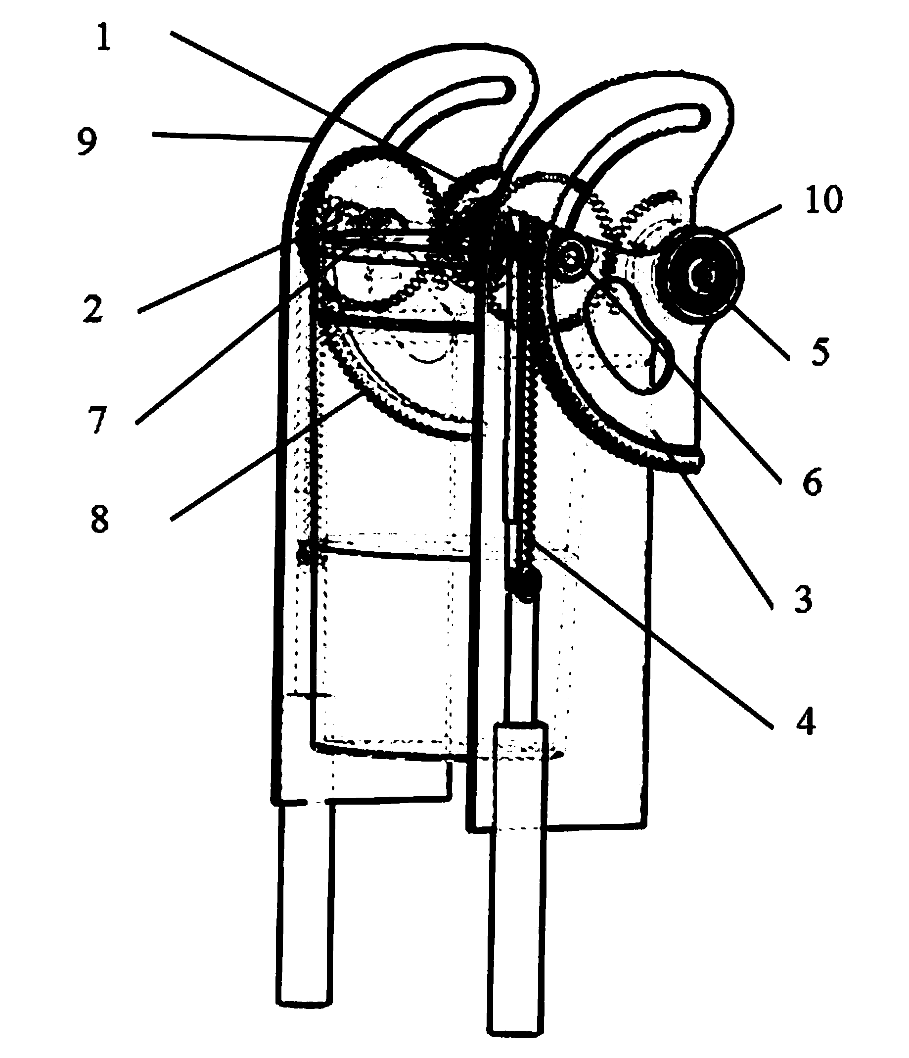
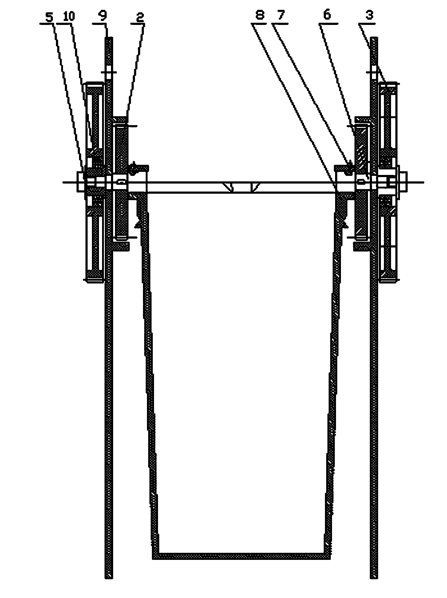
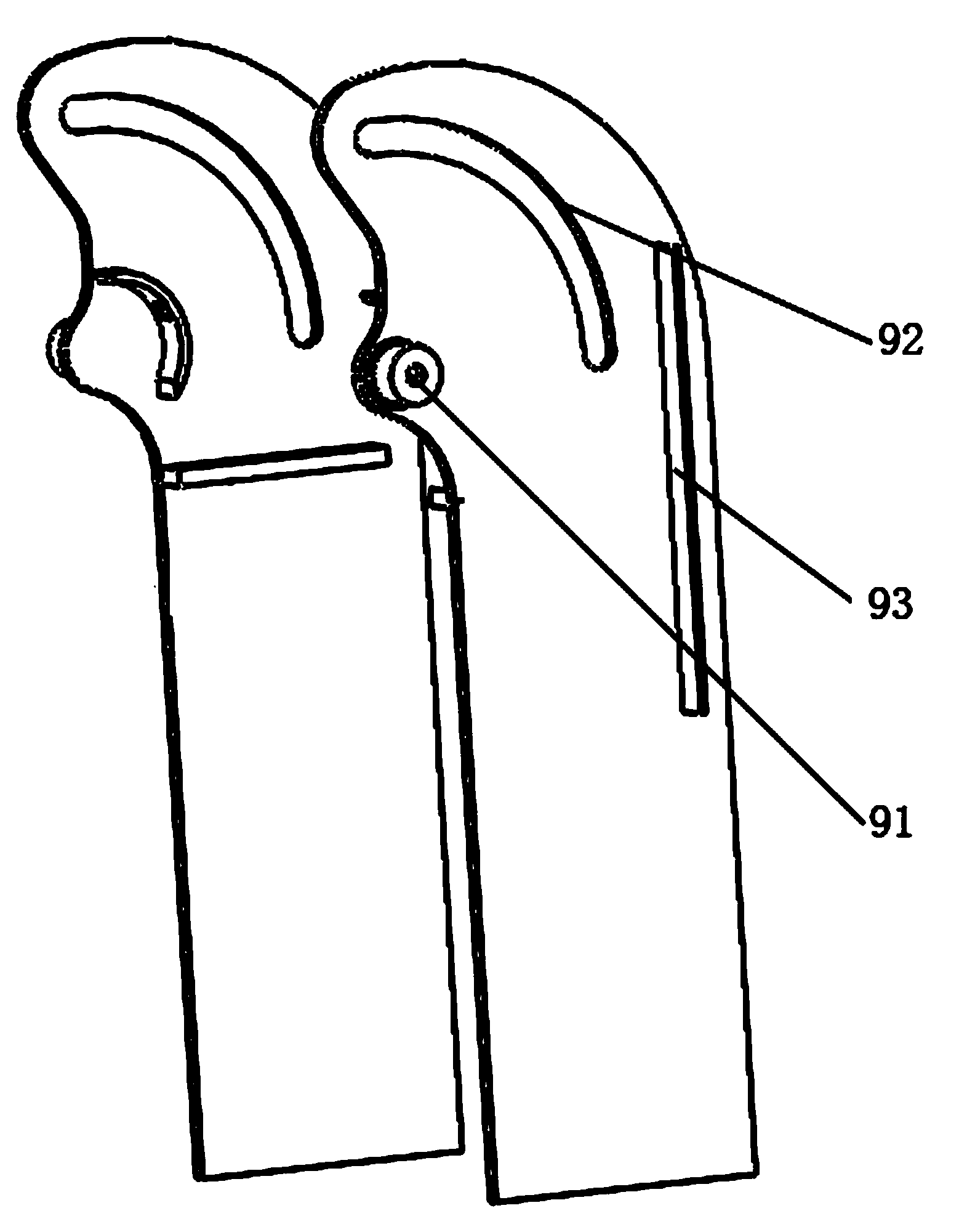
[0020] Such as Figure 1-4 As shown, the present invention includes two support plates 9 and ladles 8 arranged in parallel, and the opposite faces of the two support plates 9 are respectively provided with a cylindrical boss 91 and an arc-shaped groove centered on the center of the boss 91 92, a half-moon sun gear 1 is fixedly installed on the opposite surfaces of the two support plates 9, and the center of the sun gear 1 coincides with the center of the boss 91; a fan-shaped external gear 3 is installed on the boss 91 through a deep groove ball bearing 10 , between the outer gear 3 and the outer ring of the deep groove ball bearing 10 and between the inner ring of the deep groove ball bearing 10 and the boss 91 are interference fits, and the deep groove ball bearing 10 and the outer gear 3 are installed on the The bearing cover 5 at the end of the boss 91 is fixed. ...


PUM


Abstract

The invention discloses a gear type fixed-point tilting pouring machine. The gear type fixed-point tilting pouring machine comprises two support plates in parallel and a pouring ladle, wherein a cylindrical boss and an arc-shaped slot taking the center of the cylindrical boss as the center of a circle are formed on each of the back-to-back surfaces of the two support plates, sun gears are fixedly mounted on the opposite surfaces of the two support plates, and the center of each sun gear and the center of the corresponding boss are superimposed; an outer gear is mounted on each boss through a radial rolling bearing and is meshed with a rack, and the racks are fixedly mounted on a hydraulic cylinder; tilting shafts are mounted on the outer gears, correspond to the arc-shaped slots, and penetrate through the arc-shaped slots of the support plates to be connected with planet gears, and the planet gears are meshed with the sun gears; two pouring ladle lugs of the pouring ladle are connected with the two tilting shafts through threaded pins, respectively. The gear type fixed-point tilting pouring machine disclosed by the invention is safe and reliable and can control the tilting of the pouring ladle easily; when the gear type fixed-point tilting pouring machine is used for pouring, the pouring ladle rotates at a fixed point around an imaginary rotating shaft, the positions of a pouring ladle mouth and a pouring gate are unchanged, and the pouring quality is improved.

Description

technical field [0001] The invention relates to a fixed-point tilting pouring machine, in particular to a gear-type fixed-point tilting pouring machine. Background technique [0002] At present, in small and medium-sized foundry enterprises, especially township enterprises, the traditional foundry production process can still be seen, that is, the workers manually operate the ladle to quickly inject hot metal solution into the cavity. The working environment is bad, the pouring efficiency is low, and the product quality is difficult to be guaranteed. And adopt manual pouring method, generally can only 50-100 kilograms of molten metal each time, need labor force, labor intensity is high, and there is bigger potential safety hazard during pouring. [0003] Some current mechanical pouring devices, such as the Chinese Utility Model Patent Application No. 201320072733.7, disclose a pouring device in which a gear transmission is installed on the center of gravity of the ladle,...

Claims


Application Information

Patent Timeline
Patent Type & Authority Applications(China)
IPC IPC(8): B22D41/06
Inventor 朱石沙雷先华
Owner XIANGTAN UNIV
Why Eureka
Try Eureka