
Take-up and pay-off device and method for exhibition hall

A wire take-up and pay-off device and technology for take-up and pay-off wires, applied in the field of take-up and pay-off devices for exhibition halls, can solve problems such as occupying a large space, affecting normal use, increasing wrong wiring, etc., to achieve the effect of ensuring correct installation and novel design

Pending Publication Date: 2020-02-28
苏州和氏设计营造股份有限公司
View PDF0 Cites 0 Cited by
  • Summary
  • Abstract
  • Description
  • Claims
  • Application Information

AI Technical Summary

Problems solved by technology

During the layout process, the disordered lines will be entangled with each other, which increases the probability of wrong wiring and causes the equipment to not work properly; at the same time, the process of pulling the lines will also cause deformation or breakage, affecting normal use
At present, the take-up and pay-off setting only has one bobbin or a simple superposition of multiple bobbins, which has a single function and takes up a lot of space
When there are many lines and the lengths of the lines are not the same, it cannot be adjusted quickly

Method used


Image

  • Take-up and pay-off device and method for exhibition hall
  • Take-up and pay-off device and method for exhibition hall

Examples


Embodiment Construction

[0026] The following will clearly and completely describe the technical solutions in the embodiments of the present invention with reference to the accompanying drawings in the embodiments of the present invention. Obviously, the described embodiments are only some, not all, embodiments of the present invention. The components of the embodiments of the invention generally described and illustrated in the figures herein may be arranged and designed in a variety of different configurations. Accordingly, the following detailed description of the embodiments of the invention provided in the accompanying drawings is not intended to limit the scope of the claimed invention, but merely represents selected embodiments of the invention. Based on the embodiments of the present invention, all other embodiments obtained by those skilled in the art without making creative efforts belong to the protection scope of the present invention.

[0027] It should be noted that like numerals and let...


PUM


Abstract

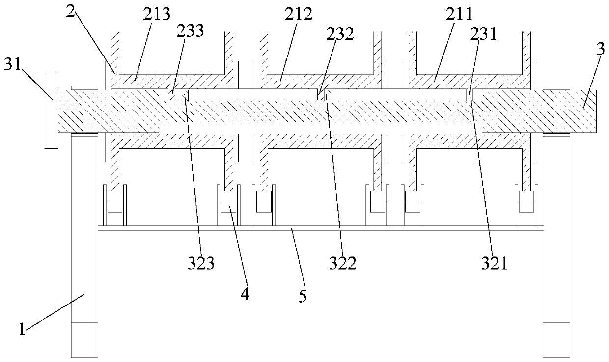
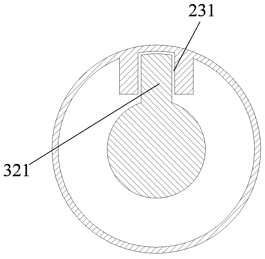
The invention relates to a take-up and pay-off device and method for an exhibition hall. A rotating shaft comprises a small-diameter part at the middle section and large-diameter parts at the two ends, a pay-off assembly comprises multiple sections of pay-off cylinders arranged in the axial direction, and a side plate of each section of pay-off cylinder is supported on a supporting round wheel; the supporting round wheels are installed on a supporting plate, the supporting plate is fixed on a frame base, and the rotating shaft penetrates through inner holes of the pay-off assembly; the inner holes at the two ends of the pay-off assembly are matched with the large-diameter parts at the two ends of the rotating shaft, and the end part of the rotating shaft is rotationally supported on the frame base; a joint part is arranged in the middle of an inner hole of each section of pay-off cylinder, each joint part is provided with a U-shaped groove in the axial direction, and the multiple U-shaped grooves are located in the same linear direction in the axial direction; and the small-diameter part of the rotating shaft is convexly provided with convex blocks matched with the U-shaped groovesof all the sections, and the multiple convex blocks are located in the same straight line direction in the axial direction. When one of the convex blocks is matched with the U-shaped groove of one pay-off cylinder, the other convex blocks are not matched with the U-shaped grooves of the pay-off cylinders; and the position of a moving rotating disc is adjusted, and the working states of differentpay-off cylinders are rapidly switched.

Description

technical field [0001] The invention relates to a wire retracting and releasing device for an exhibition hall and a method thereof. Background technique [0002] At present, the multimedia equipment and lighting devices in the exhibition hall require a large number of wires to transmit electric energy and communication cables to transmit signals. During the layout process, the disordered lines will be entangled with each other, which increases the probability of wrong wiring and causes the equipment to not work normally; at the same time, the process of pulling the lines will also cause deformation or breakage, affecting normal use. At present, the take-up and pay-off setting only has one bobbin or a simple superposition of multiple bobbins, which has a single function and takes up a lot of space. When there are many lines and the lengths of the lines are not the same, it cannot be adjusted quickly. Contents of the invention [0003] The object of the present invention i...

Claims


Application Information

Patent Timeline
IPC IPC(8): B65H75/38B65H75/44
CPCB65H75/38B65H75/44B65H75/4457B65H2701/34
Inventor 吴景贤张郁李之超
Owner 苏州和氏设计营造股份有限公司
Learn More