
Tunnel track laying machine and hydraulic cylinder support arm for track laying machine

A technology of track laying machine and hydraulic cylinder, which is applied to roads, tracks, laying tracks, etc., and can solve problems such as stagnation of track paving process, impact on project progress, and narrow space

Pending Publication Date: 2020-02-28
HENAN DONGQI MACHINERY
View PDF0 Cites 3 Cited by
  • Summary
  • Abstract
  • Description
  • Claims
  • Application Information

AI Technical Summary

Problems solved by technology

The space in the tunnel is small, and there are many risk factors, inconvenient operation, long working time and other unfavorable factors in changing the span and structure of the tunnel track-laying machine in the tunnel. Once the tunnel track-laying machine in the tunnel is stopped, the entire track paving process will be stagnant , causing idle work
In the existing technology center, the tunnel track-laying machine needs to be hoisted by the gantry crane to change the span, or the tunnel track-laying machine is disassembled when the span is changed, so the efficiency is very low; In the transition situation, the door crane must be disassembled and reassembled every time the transition is made, which affects the progress of the project

Method used


Image

  • Tunnel track laying machine and hydraulic cylinder support arm for track laying machine
  • Tunnel track laying machine and hydraulic cylinder support arm for track laying machine
  • Tunnel track laying machine and hydraulic cylinder support arm for track laying machine

Examples


Embodiment Construction

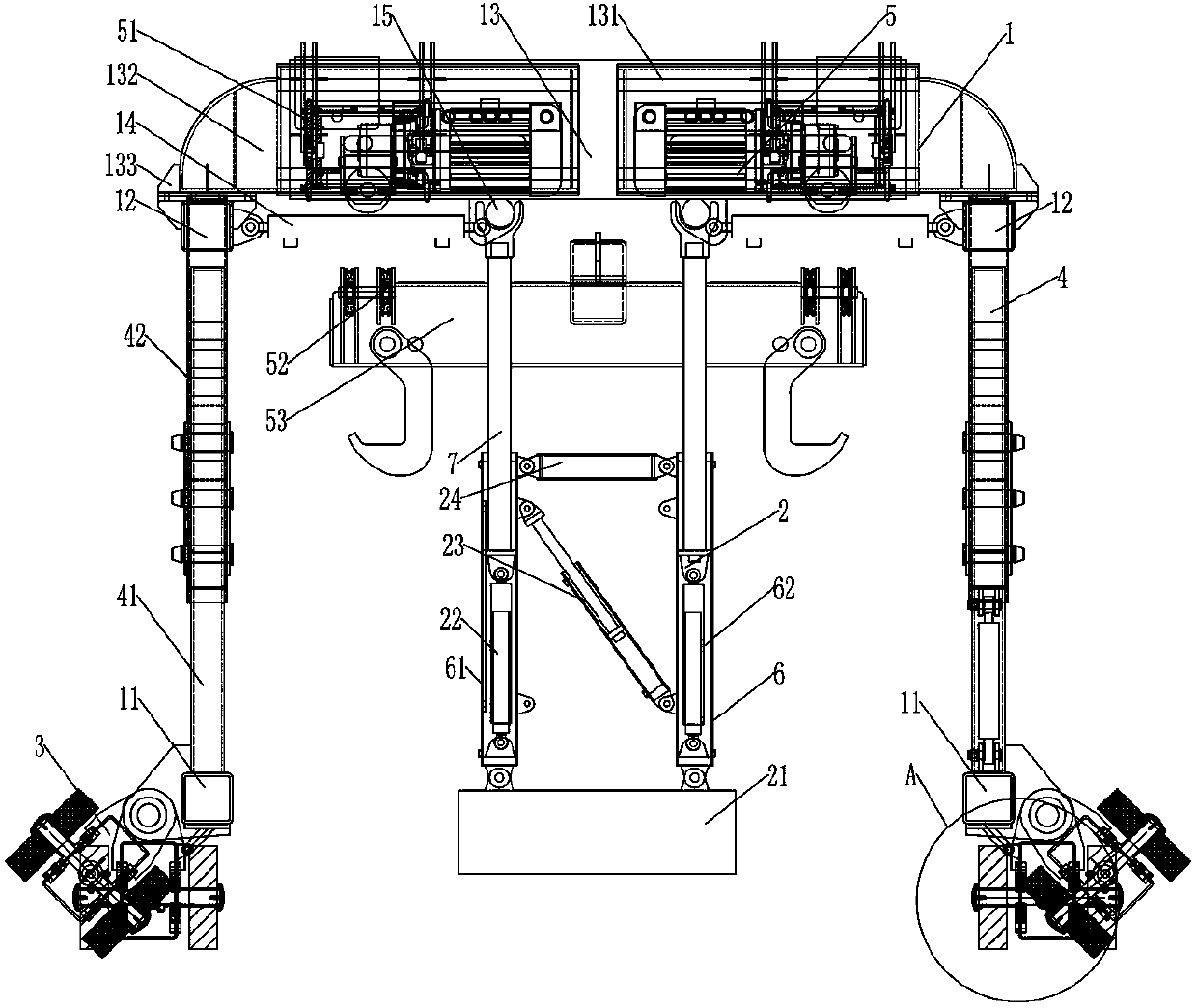
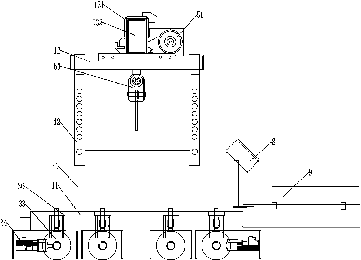
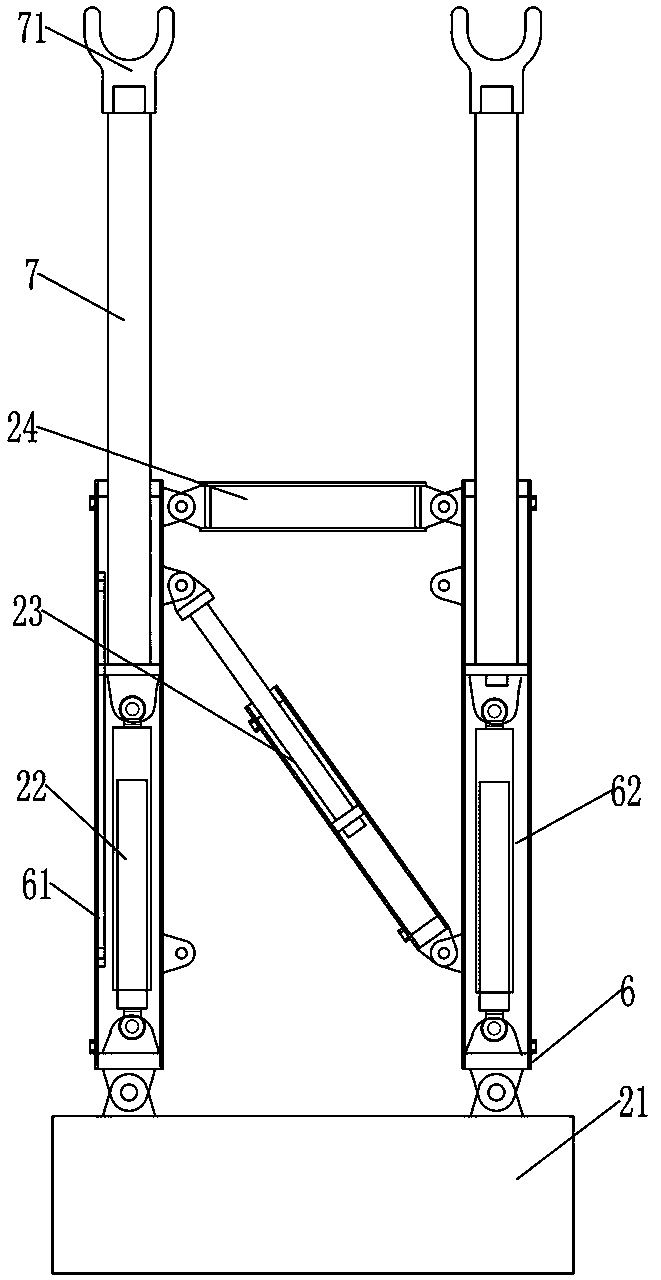
[0020] Such as Figure 1-6 As shown, a tunnel track-laying machine and a hydraulic cylinder support arm for a track-laying machine include a hydraulic cylinder support arm 2 for a tunnel track-laying machine 1 and an auxiliary track-laying machine. The bottom ends of the two ends of the beam 11 are respectively provided with a traveling mechanism 3, and the traveling mechanism 3 includes a traveling wheel support 31, and the traveling wheel support 31 is provided with a bearing, and the traveling wheel support 31 is connected with a transmission shaft 32 through the bearing rotation, and the transmission The shaft 32 is rotatable relative to the road wheel bracket 31 . The two ends of the transmission shaft 32 extend out of the road wheel bracket 31 respectively, and the two ends of the transmission shaft 32 are respectively fixed with a road wheel 33, and the outer side of the road wheel bracket 31 is fixed with a frequency conversion motor 34, and the transmission output sha...


PUM


Abstract

The invention discloses a tunnel track laying machine and a hydraulic cylinder support arm for the track laying machine, and comprises a tunnel track laying machine and a hydraulic cylinder support arm for assisting the track laying machine. The tunnel track laying machine comprises lower end beams which are horizontally arranged at intervals, walking mechanisms are arranged at the bottom ends ofthe two ends of the lower end beams correspondingly, supporting legs which are vertically arranged are fixed to the top ends of the end parts of the lower end beams, and the top ends of the support legs are fixedly provided with upper end beams parallel to the lower end beams; and a main beam of the track laying machine is arranged between every two upper end beams, the two ends of the main beamsare fixed to the upper ends of the upper end beams correspondingly, the bottom ends of the main beams are fixed to support beams which are arranged in parallel at intervals, and the main beams are provided with lifting mechanisms. The hydraulic cylinder support arm comprises a rectangular chassis, lower support arms are arranged at the four corners of the top end of the chassis, hydraulic cylinders are arranged in the lower support arms, the hydraulic cylinders are hinged to the bottom ends of the lower support arms, and the free ends of the hydraulic cylinders are hinged to the bottom ends ofupper support arms. The tunnel track laying machine and the hydraulic cylinder support arm for the track laying machine are simple in structure and convenient to operate, and the working efficiency of tunnel laying is improved.

Description

technical field [0001] The invention relates to the technical field of tunnel hoisting machinery design, in particular to a tunnel track-laying machine and a hydraulic cylinder support arm for the track-laying machine. Background technique [0002] In the process of tunnel traffic construction, the track pavement project is in the middle of the civil engineering and equipment installation projects in terms of construction schedule. It is the immediate process of civil engineering and the immediate process of other equipment installation projects. It has a huge impact on the progress of subsequent equipment installation and commissioning. In the various processes of tunnel track installation engineering construction, the laying of inner rails and concrete pouring in the tunnel are the key processes, and it is also the most important and difficult to control part of the production schedule. As the most critical equipment in this link, the technology of tunnel track laying mach...

Claims


Application Information

Patent Timeline
IPC IPC(8): E01B29/16
CPCE01B29/16E01B2203/14E01B2203/017
Inventor 张春丽王立建王一晓吉洋李元恒
Owner HENAN DONGQI MACHINERY
Features
  • Generate Ideas
  • Intellectual Property
  • Life Sciences
  • Materials
  • Tech Scout
  • Unparalleled Data Quality
  • Higher Quality Content
  • 60% Fewer Hallucinations
Learn More