Current induction device

A current sensing and current clamp technology, applied in the field of current sensing testing, can solve the problems of low work efficiency, time-consuming, high risk and hidden dangers, and achieve the effects of convenient operation, reduced wiring work, and increased control distance.

Pending Publication Date: 2020-02-28
GUANGDONG POWER GRID CO LTD +1
View PDF0 Cites 1 Cited by
  • Summary
  • Abstract
  • Description
  • Claims
  • Application Information

AI Technical Summary

Problems solved by technology

[0004] The present invention overcomes the problems described in the above-mentioned background technology that during the measurement operation process, the measurement personnel need to frequently climb up to carry out high-altitude operations to install the measurement current clamp, and the completion of the test process of a capacitor group is time-consuming, laborious, low in work efficiency, and high in hidden dangers problem, providing a current sensing device

Method used


Image

  • Current induction device
  • Current induction device

Examples


Embodiment Construction

[0020] The accompanying drawings are for illustrative purposes only, and should not be construed as limitations on this patent; in order to better illustrate this embodiment, certain components in the accompanying drawings will be omitted, enlarged or reduced, and do not represent the size of the actual product; for those skilled in the art It is understandable that some well-known structures and descriptions thereof may be omitted in the drawings. The positional relationship described in the drawings is for illustrative purposes only, and should not be construed as a limitation on this patent.

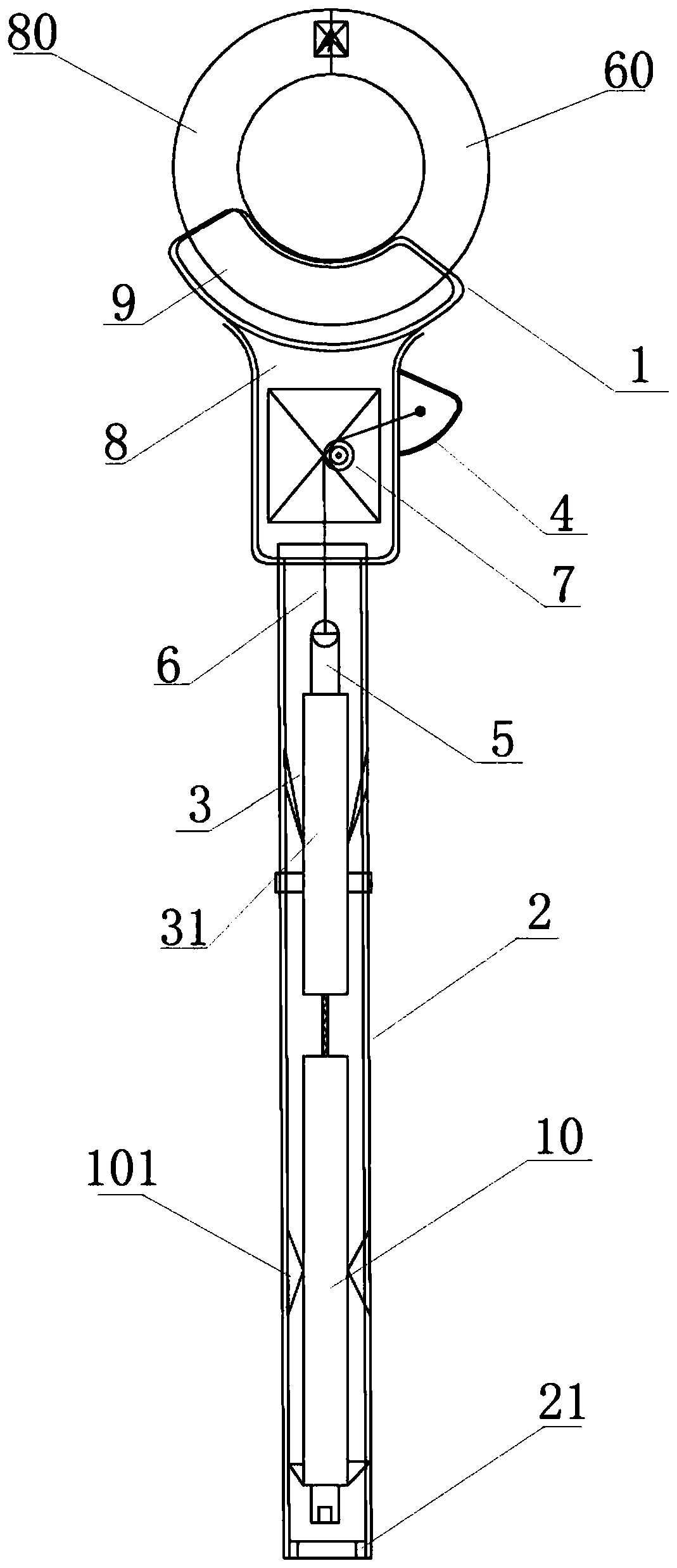
[0021] Such as figure 1As shown, it is a current clamp 1 installation device, including the current clamp 1 and the current clamp 1 wrench located on the side wall of the current clamp 1 and controlling the opening and closing of the current clamp 1. One side of the current clamp 1 is connected with a hollow The insulating rod 2 is provided with a lithium battery 10, a pen-type elect...


PUM


Abstract

The invention provides a current induction device. The current induction device comprises a current clamp and a current clamp wrench which is arranged on the side wall of the current clamp and controls opening and closing of the current clamp, wherein one side of the current clamp is connected with a hollow insulating rod; a power supply, an electric push rod and a control module for controlling the electric push rod to stretch out and draw back are arranged in the insulating rod; a push rod of the electric push rod is connected with the current clamp wrench by means of a traction piece; and the power supply is electrically connected with the electric push rod by means of the control module. The current induction device achieve the effect of directly installing the current clamp at a corresponding test position on the ground, does not require any high-altitude operation in the whole test process, has no connecting cable, and realizes the purpose of zero-risk safety measurement.

Description

technical field [0001] The invention relates to the field of current induction testing, and more particularly, to a current induction device. Background technique [0002] In order to reduce reactive power loss, the power system usually adopts the method of parallel compensation capacitor bank to improve the power factor. In order to meet the requirements of automatic tracking and real-time compensation of the power system, the reactive power compensation device must frequently switch and cut reactive power compensation capacitors. group, and the switching and switching operations of the capacitor group will generate current and overvoltage shocks, causing capacitor damage. In order to ensure the normal operation of the equipment, capacitors need to be tested regularly, and it is very important to find capacitor defects early and avoid fault expansion. The installation height of the capacitors of the capacitor bank is generally high, some as high as 4 to 5 meters. The test ...

Claims


Application Information

Patent Timeline
Patent Type & Authority Applications(China)
IPC IPC(8): G01R19/00G01R15/00
CPCG01R15/00G01R19/0092
Inventor 朱子龙杨炎宇郭小凯李莹梁育雄周锋李鹏
Owner GUANGDONG POWER GRID CO LTD
Why Eureka
Try Eureka