Crane track detection device

A track detection and crane technology, applied in the direction of measuring devices, optical devices, instruments, etc., can solve problems such as drift, danger, and large volume of total stations, and achieve the effect of improving stability, preventing rollover, and realizing safe measurement

Inactive Publication Date: 2014-05-07
SHANGHAI UNIV OF ENG SCI +1
View PDF6 Cites 11 Cited by
  • Summary
  • Abstract
  • Description
  • Claims
  • Application Information

AI Technical Summary

Problems solved by technology

The laser alignment measurement method has a high detection accuracy when the measurement distance is small. However, when the track length exceeds 50 meters, the laser beam will be affected by many factors, resulting in drift, and the detection effect is not ideal.
[0006] A relatively high accuracy can be obtained by measuring with a total station. However, there are two disadvantages in the existing total station measurement method: one is that the total station needs to be fixed on the track to aim at the reflector, and the working environment is established in the air. It is necessary to climb to the crane track for inspection, the working environment is complex and dangerous, and because the total station is large in size and heavy in weight, it is very inconvenient to build a station before measurement
The actual on-site environment is complex and changeable, and it is often not easy to build a station in the air
Second, because the total station needs to be fixed on one track for measurement, when measuring another track, it is often necessary to move the total station to another track to rebuild the station, which undoubtedly increases the workload and difficulty of the inspection work
Moreover, since the position of the total station needs to be moved during the detection process, the measurement of the two tracks is in a different coordinate system. When detecting the joint parameters of the two tracks, the transformation and unification of the coordinate system is required, which increases the complexity of data processing. sex

Method used


Image

  • Crane track detection device
  • Crane track detection device
  • Crane track detection device

Examples


Embodiment Construction

[0033] In order to make the object, technical solution and advantages of the present invention clearer, the technical solution of the present invention will be further described in detail below in conjunction with the embodiments and accompanying drawings.

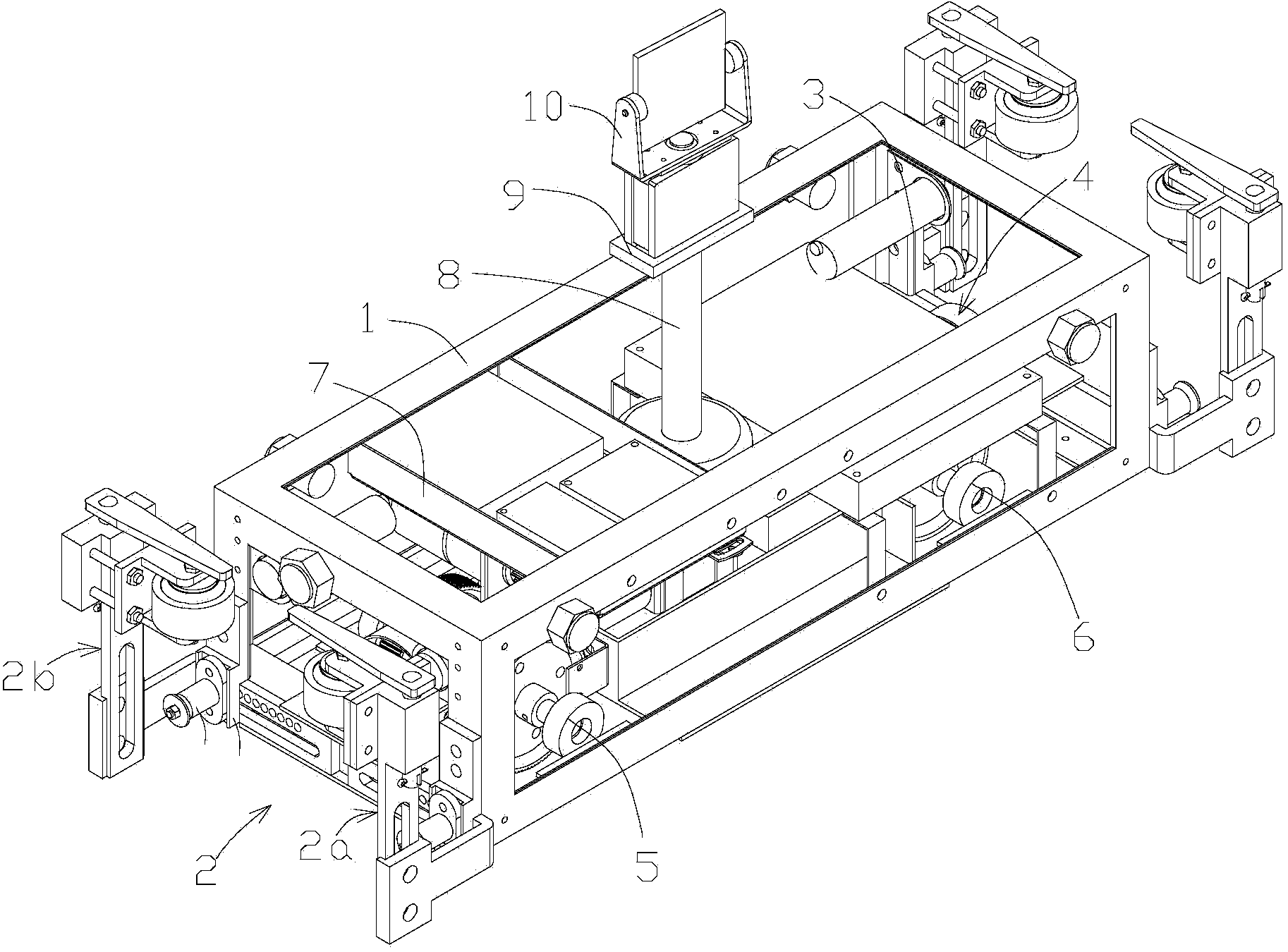
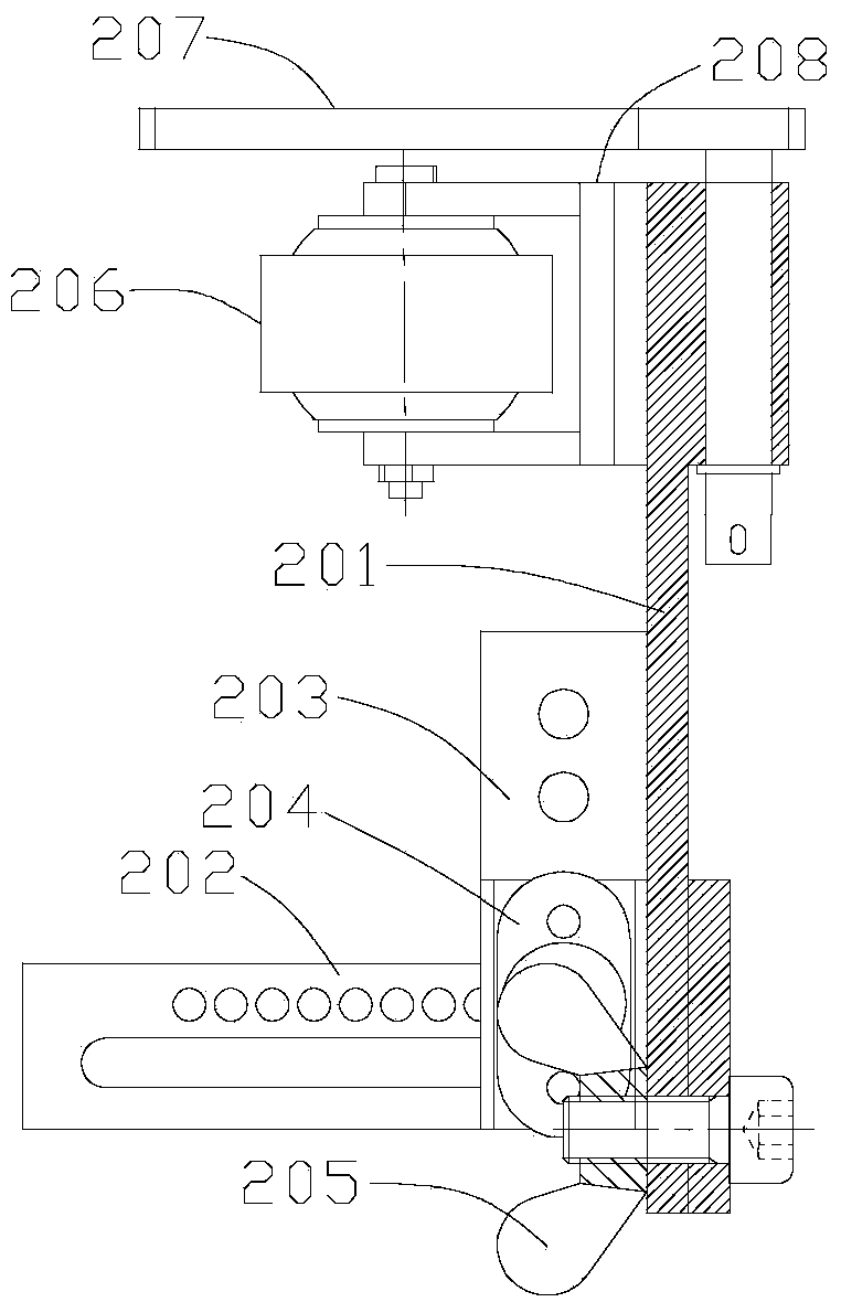
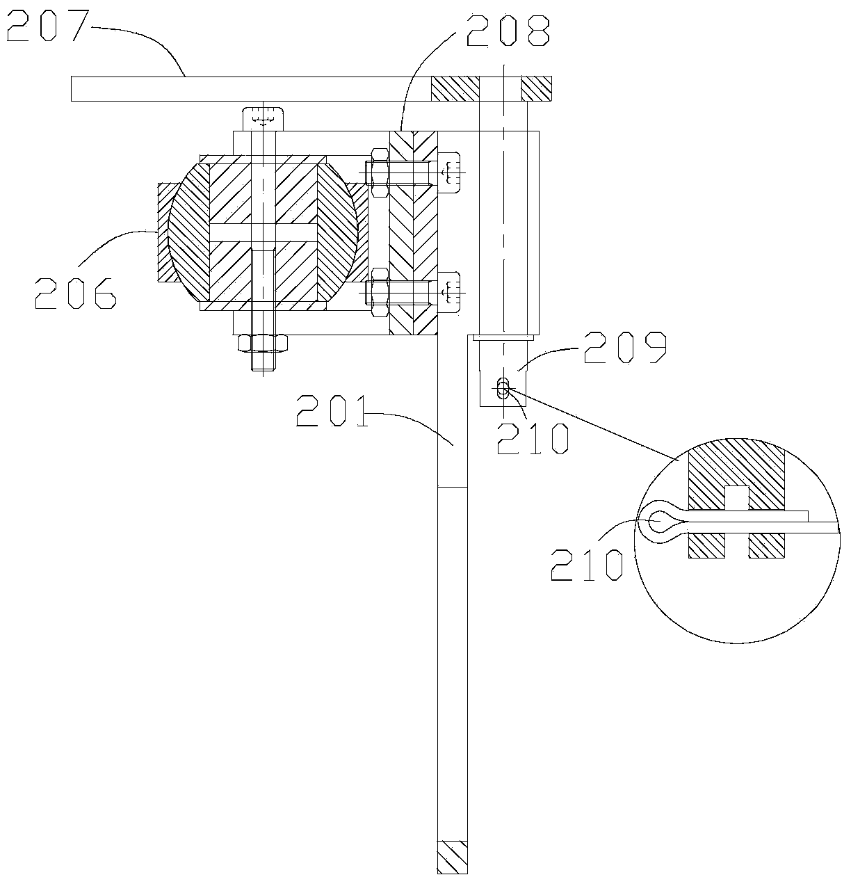
[0034] refer to figure 1 , a crane track detection device provided by the present invention is used to move along the crane track and transmit light wave signals to the total station, including a vehicle frame 1 and a front panel that is arranged under the vehicle frame 1 and can be rotated by a driving mechanism. Wheels 5 and rear wheels 6, wherein the two ends of the vehicle frame 1 are respectively provided with guide mechanisms 2 for sliding along the side of the track, and the vehicle frame 1 is also provided with detection components for sending light wave signals to the total station. The guide mechanism 2 is used to ensure that the forward direction of the trolley is along the laying direction of the track, and ens...


PUM


Abstract

The invention discloses a crane track detection device. The crane track detection device is used for moving along a crane track and transmitting light-wave signals to a total station and comprises a frame, front wheels and rear wheels, the front wheels and the rear wheels are arranged below the frame and driven by a driving mechanism to rotate, the two ends of the frame are provided with guide mechanisms which slide along the side faces of the track, and a detection component which is used for sending the light-wave signals to the total station is further arranged on the frame. The crane track detection device has the advantages of being high in safety, easy to operate, simple in structure and the like in track detection of cranes.

Description

technical field [0001] The invention relates to a crane track detection device, which belongs to the technical field of crane track detection. Background technique [0002] In the field of modern industrial production, cranes play a pivotal role in material handling. With the rapid development of modern industry, the lifting capacity of cranes is constantly increasing. At the same time, the overall size of cranes is becoming larger and larger. rapidly increasing. As an important branch of the crane, the bridge crane is prone to the phenomenon of "gnawing the rail" during the working process (the so-called "rail gnawing" refers to the contact between the wheel rim and the side of the track during the operation of the bridge crane cart or trolley. , produce horizontal lateral thrust, causing friction and wear between the wheel rim and the track), "gnawing rails" will reduce the service life of the wheels and tracks, increase running resistance, may burn out the motor or twist...

Claims


Application Information

Patent Timeline
IPC IPC(8): G01B11/00
Inventor 刘伟程维明孔庆彬肖静文邵利明陈斌
Owner SHANGHAI UNIV OF ENG SCI
Why Eureka
Try Eureka