
Test device and test method capable of simulating water pressure in tunnel

A test device and pressure technology, used in measuring devices, machine/structural components testing, instruments, etc., can solve problems such as very high requirements for hole plugging, inability to continue testing, and damage to the construction environment, so as to ensure the construction and operation of the project. Safety, good economic and technical benefits, the effect of flexible operation

Active Publication Date: 2017-01-25
CHINA INST OF WATER RESOURCES & HYDROPOWER RES
View PDF10 Cites 31 Cited by
  • Summary
  • Abstract
  • Description
  • Claims
  • Application Information

AI Technical Summary

Problems solved by technology

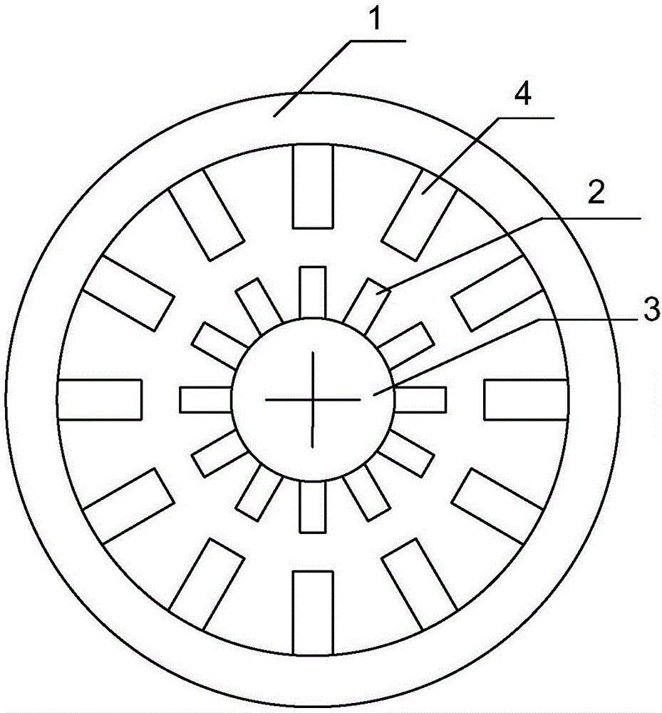
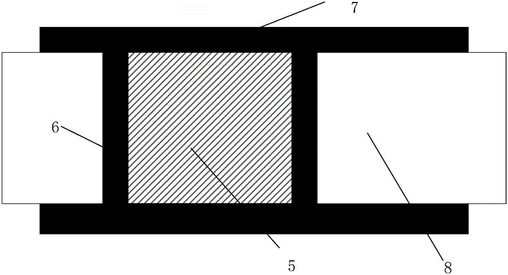
The advantage of this method is that it completely simulates the stress of the lining 7 under water pressure during the operation period, and no uneven water pressure will be generated on the lining. In addition, if the in-situ water injection test is carried out, the transportation and continuous supply of water and the corresponding supporting facilities will greatly increase the difficulty of the test, and even due to the closedness of the tunnel, the two water blocking ends will be in an isolated state , there will also be problems in the treatment of water leakage when there are cracks in the lining, and the drainage after the test will also cause damage to the surrounding construction environment

Method used


Image

  • Test device and test method capable of simulating water pressure in tunnel
  • Test device and test method capable of simulating water pressure in tunnel
  • Test device and test method capable of simulating water pressure in tunnel

Examples


Embodiment Construction

[0044] The present invention will be described in further detail below in conjunction with the accompanying drawings and embodiments.

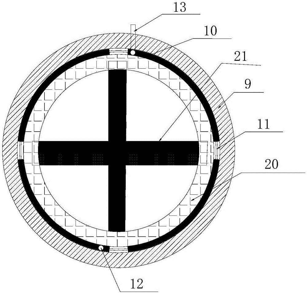
[0045] Such as Figure 3-7 As shown, the test device for simulating water pressure in a tunnel of the present invention includes a load loading mechanism, a monitoring system, and a reaction force mechanism;

[0046] The load loading mechanism includes a plurality of flexible containers 10, connecting pipes 11, and liquid filling pumps 15. Connectors are provided at both ends of the flexible containers 10, and the two flexible containers are connected through the connecting pipes 11, and the two flexible containers are connected in pairs. After the pipes are connected, the outer side 16 of each flexible container 10 is arranged on the ring section of the lining 9, the flexible container near the lower end of the lining ring section is provided with a liquid injection pipe 12, and the flexible container near the upper end of the lining ring sec...


PUM


Abstract

The invention provides a test device and a test method capable of simulating water pressure in a tunnel. The test device comprises a load loading mechanism, a monitoring system and a counter-force mechanism. The load loading mechanism comprises a plurality of flexible cells and a liquid filling pump, wherein every two adjacent flexible cells are communicated with each other to form a closed structure body fitting a lining ring section, and a liquid filling pipe on one of the flexible cells is connected with a liquid outlet of the liquid filling pump. The monitoring system comprises stressometers, steel bar meters, fiber grating sensors, multi-point displacement indicators, osmometers and joint meters, wherein the stressometers and the steel bar meters are embedded into a lining, the fiber grating sensors are arranged on the inner and outer surfaces of the lining, the multi-point displacement indicators, the osmometers and the joint meters are embedded into a surrounding rock, and the signal output end of each sensor is connected with a data acquisition unit. The counter-force mechanism comprises a counter-force H-steel piece and a counter-force supporting piece which are fixedly connected with each other, one side of each flexible cell is arranged correspondingly to the lining ring section, and the counter-force supporting piece supports the other side of each flexible cell. The test device is capable of simulating detection of the concrete lining construction quality and prestress applying effect during operation of the tunnel filled with water.

Description

technical field [0001] The invention relates to a test device and method for simulating water pressure in a tunnel, belonging to the technical field of water conservancy and hydropower engineering. Background technique [0002] With the vigorous construction of national water transmission projects, ring-anchor prestressed concrete lining technology is generally adopted for pressurized water transmission tunnels with poor surrounding rock conditions and thin covering layers, and ring-anchor prestressed concrete lining can be divided into bonded There are two kinds of ring anchor prestressed concrete lining and unbonded ring anchor prestressed concrete lining. [0003] During the design and construction of ring-anchored prestressed concrete lining, it is generally necessary to conduct model or field construction tests to monitor the stress and crack development of the lining during the construction and operation periods, so as to ensure the safety of project construction and o...

Claims


Application Information

Patent Timeline
Patent Type & Authority Applications(China)
IPC IPC(8): G01M99/00
CPCG01M99/007
Inventor 汪小刚姜龙赵宇飞曹瑞琅王玉杰贾志欣皮进刘立鹏林兴超段庆伟郑理峰
Owner CHINA INST OF WATER RESOURCES & HYDROPOWER RES
Learn More