Self-adaptive direction-finding antenna for measuring signal direction of mobile phone and measuring method thereof

A technology of self-adaptive measurement and mobile phone signal, applied to direction finders using radio waves, radio wave direction/deviation determination systems, antennas, etc. Universal requirements and other issues to achieve the effect of flexible adaptation

Pending Publication Date: 2020-02-28
福州锐迪优通讯科技有限公司
View PDF0 Cites 3 Cited by
  • Summary
  • Abstract
  • Description
  • Claims
  • Application Information

AI Technical Summary

Benefits of technology

This technology allows an electronic device (such as a smartphone) with its own orientation sensor that automatically adjusts itself based on how far it's from other devices or nearby objects. It makes sure they receive better communication quality by providing more accurate location data than traditional methods like GPS.

Problems solved by technology

The patented technique described involves improving wireless network performance by utilizing advanced technologies like digital subscriber loop (DSL) protocols and code division multiple access techniques called xorations. These improvements help improve data transmission rates over long distances without sacrificing reliance capabilities. Additionally, these improved systems aim to accurately measure both the orientation of the transmitting handset and the reception of the intended call from another party simultanously.

Method used


Image

  • Self-adaptive direction-finding antenna for measuring signal direction of mobile phone and measuring method thereof
  • Self-adaptive direction-finding antenna for measuring signal direction of mobile phone and measuring method thereof

Examples


Embodiment 1

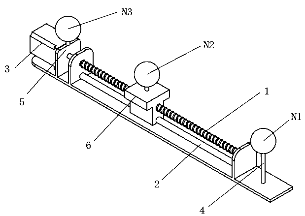
[0043] Such as figure 1As shown, this embodiment proposes a single-dimensional adaptive direction-finding antenna for measuring the signal direction of a mobile phone, including three antenna units N1, N2, N3, a screw rod 1, a slide rail 2, a servo motor 3, and a first fixing seat 4 , the second fixed seat 5 and the sliding seat 6; the three antenna units N1, N2, and N3 are respectively fixed on the first fixed seat 4, the second fixed seat 5 and the sliding seat 6; the two fixed seats are respectively fixed on the slide rails 2, the screw rod 1 is parallel to the top of the slide rail 2, and the sliding seat 6 is provided with a slide rail sleeve hole and a threaded hole, which are respectively set on the slide rail 2 and the screw rod 1, and one end of the screw rod 1 is connected to the servo motor 3. The rotation is driven by the servo motor 3 to adjust the position of the sliding seat 6 . In this implementation solution, the distance between the direction finding antenna...

Embodiment 2

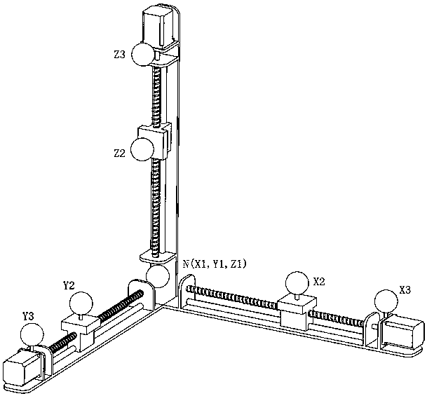
[0045] Such as figure 2 As shown, this embodiment proposes a three-dimensional adaptive direction-finding antenna for measuring the signal direction of a mobile phone, which is composed of three groups of single-dimensional adaptive direction-finding antennas in Embodiment 1. The antenna unit at the intersecting end of the direction-finding antenna is shared as a common reference antenna unit.

[0046] Specifically, the antenna units on the three groups of antennas are X1, X2, X3; Y1, Y2, Y3; Z1, Z2, Z3; where X1, Y1, and Z1 are shared, as a common reference antenna unit, set to N; X2 , Y2, and Z2 all perform single-dimensional sliding under the control of their respective servo motors to complete the variable distance operation in their respective dimensions; X3, Y3, and Z3 are fixed.

[0047] N point and X3 point, N point and Y3 point, N point and Z3 point have the same spacing, set as D3, select the maximum value according to the required size; N point and X2 point, N poi...

Embodiment 3

[0051] This embodiment introduces a method for determining the signal direction of a mobile phone with a three-dimensional adaptive direction-finding antenna, including steps:

[0052] S1. Set the frequency of the target source;

[0053] S2. The system control software automatically calculates D2 according to the frequency of the target source, the calculation formula D2 = C / (2*f), C is the propagation speed of electromagnetic waves in the atmosphere, and f is the center frequency of the target source;

[0054] S3. The system control software controls the servo motor to drive the screw to rotate so that the sliding seat moves to a position D2 away from point N;

[0055] S4. The system starts direction finding: on the X axis, measure the phase difference θ1 received by N and X2, and the phase difference θ2 received by N and X3; θ1 is a rough value, a unique value, and there is no multi-value; θ2 is an exact value, including multiple values;

[0056] S5. According to the calcu...


PUM


Abstract

The invention discloses a self-adaptive direction finding antenna used for measuring a signal direction of a mobile phone and a measuring method thereof. A single-dimensional self-adaptive direction finding antenna and a three-dimensional self-adaptive direction finding antenna are included. The single-dimensional self-adaptive direction finding antenna comprises three antenna units, a screw rod,a slide rail, a servo motor, two fixed seats and a slide seat. The three antenna units are fixedly arranged on the two fixed seats and the sliding seat. The two fixed seats are fixed to two ends of the sliding rail respectively and sleeve the sliding rail and the screw rod. One end of the screw rod is connected with a servo motor and is driven by the servo motor to rotate, and a position of the sliding seat is adjusted. The three-dimensional self-adaptive direction-finding antenna is composed of three groups of single-dimensional self-adaptive direction-finding antenna end portions which are vertical to each other, and an antenna unit at an intersected end of the three groups of self-adaptive direction-finding antennas is shared as a common reference antenna unit. In the invention, a distance between the direction-finding antennas can be changed according to working frequency of a signal whose direction needs to be found, and a purpose of flexibly adapting to signals with different frequencies is achieved.

Description


Claims


Application Information

Patent Timeline
Owner 福州锐迪优通讯科技有限公司
Why Eureka
Try Eureka