
Outdoor power equipment box

A power equipment box, outdoor technology, applied in electrical components, substation/distribution device housing, substation/switch layout details, etc., can solve the problems of unstable operation of power equipment, high temperature of power equipment box, influence of power equipment, etc. To prevent damage, improve the efficiency of heat absorption, improve the effect of firmness

Active Publication Date: 2020-02-28
江苏鸿康电器有限公司
View PDF5 Cites 4 Cited by
  • Summary
  • Abstract
  • Description
  • Claims
  • Application Information

AI Technical Summary

Problems solved by technology

[0002] At present, with the rapid development of the economy, power equipment is becoming more and more popular in various regions, which brings a lot of convenience to people's life and ensures the electricity consumption of people's daily life. The outdoor power equipment box is used to carry out some power equipment The loaded box not only ensures the normal operation of the power equipment, but also protects the power equipment. However, when the outdoor power equipment box is used today, the temperature inside the power equipment box is too high due to the hot weather. high
[0003] The existing power equipment box usually uses the fan to drive the air flow inside the box to dissipate heat. However, when cooling in this way, a large amount of dust will enter the inside of the box, which will affect the power equipment and cause power failure. The device is unstable

Method used


Image

  • Outdoor power equipment box
  • Outdoor power equipment box
  • Outdoor power equipment box

Examples


Embodiment Construction

[0027] The following will clearly and completely describe the technical solutions in the embodiments of the present invention with reference to the accompanying drawings in the embodiments of the present invention. Obviously, the described embodiments are only some, not all, embodiments of the present invention. Based on the embodiments of the present invention, all other embodiments obtained by persons of ordinary skill in the art without making creative efforts belong to the protection scope of the present invention.

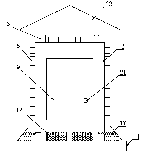
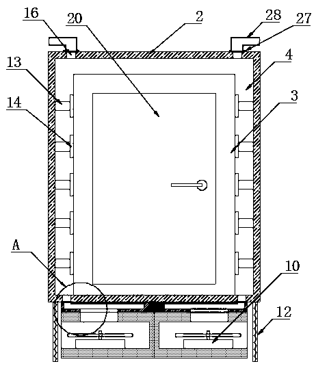
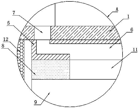
[0028] according to Figure 1-6 The outdoor power equipment box shown includes a base 1, an outer box 2 is arranged on the top of the base 1, a bearing mechanism is arranged between the outer box 2 and the base 1, and the outer box 2 is arranged inside There is an inner box 3, a diffuser cavity 4 is formed between the outer box 2 and the inner box 3, and a heat dissipation mechanism is arranged at the bottom of the outer box 2;

[0029] The heat dissipation m...


PUM


Abstract

The invention discloses an outdoor power equipment box and specifically relates to the technical field of outdoor equipment box. The outdoor power equipment box comprises a base. An outer box body isarranged at the top of the base; a bearing mechanism is arranged between the outer box body and the base; an inner box body is arranged in the outer box body; an air dissipation cavity is formed between the outer box body and the inner box body; and a heat dissipation mechanism is arranged at the bottom of the outer box body. The outdoor power equipment box is provided with the heat dissipation mechanism and heat conduction mechanisms; through the multiple heat conduction mechanisms, heat can be absorbed into the air dissipation cavity and on the outer box body; at the same time, a fan is usedto drive air to flow into the air dissipation cavity so as to dissipate heat of the inner box body; and when the inner box body is subjected to heat dissipation, air cannot enter the inner box body,so that impurities or dusts can be effectively prevented from being brought into the inner box body or static electricity is prevented from being generated in the inner box body, and the working safety of power equipment in the inner box body can be effectively improved.

Description

technical field [0001] The invention relates to the technical field of outdoor equipment boxes, and more specifically, the invention relates to an outdoor power equipment box. Background technique [0002] At present, with the rapid development of the economy, power equipment is becoming more and more popular in various regions, which brings a lot of convenience to people's life and ensures the electricity consumption of people's daily life. The outdoor power equipment box is used to carry out some power equipment The loaded box not only ensures the normal operation of the power equipment, but also protects the power equipment. However, when the outdoor power equipment box is used today, the temperature inside the power equipment box is too high due to the hot weather. high. [0003] The existing power equipment box usually uses the fan to drive the air flow inside the box to dissipate heat. However, when cooling in this way, a large amount of dust will enter the inside of ...

Claims


Application Information

Patent Timeline
Patent Type & Authority Applications(China)
IPC IPC(8): H02B1/46H02B1/56H02B1/28H02B1/20H02G3/22
CPCH02B1/46H02B1/565H02B1/28H02B1/20H02G3/22
Inventor 范希营
Owner 江苏鸿康电器有限公司
Learn More