Practical circuit for controlling output voltage and current of charger through adopting PWM mode

A technology of output voltage and mode control, applied in charging/discharging current/voltage regulation, battery circuit devices, circuit devices, etc., can solve problems such as automatic control cannot be realized, and achieve high reliability, simple circuit, and low price.

Pending Publication Date: 2020-02-28
合肥钦力电子有限公司
View PDF0 Cites 0 Cited by
  • Summary
  • Abstract
  • Description
  • Claims
  • Application Information

AI Technical Summary

Problems solved by technology

For chargers, adjustable voltage means adjustable current, but this adjustable voltage and current must be automatically controlled, and the output voltage adjustment of the finished switching power supply is often realized through the adjustment of the analog potentiometer, which cannot be realized. Automatic control, which requires us to modify the circuit

Method used


Image

  • Practical circuit for controlling output voltage and current of charger through adopting PWM mode
  • Practical circuit for controlling output voltage and current of charger through adopting PWM mode

Examples


Embodiment 1

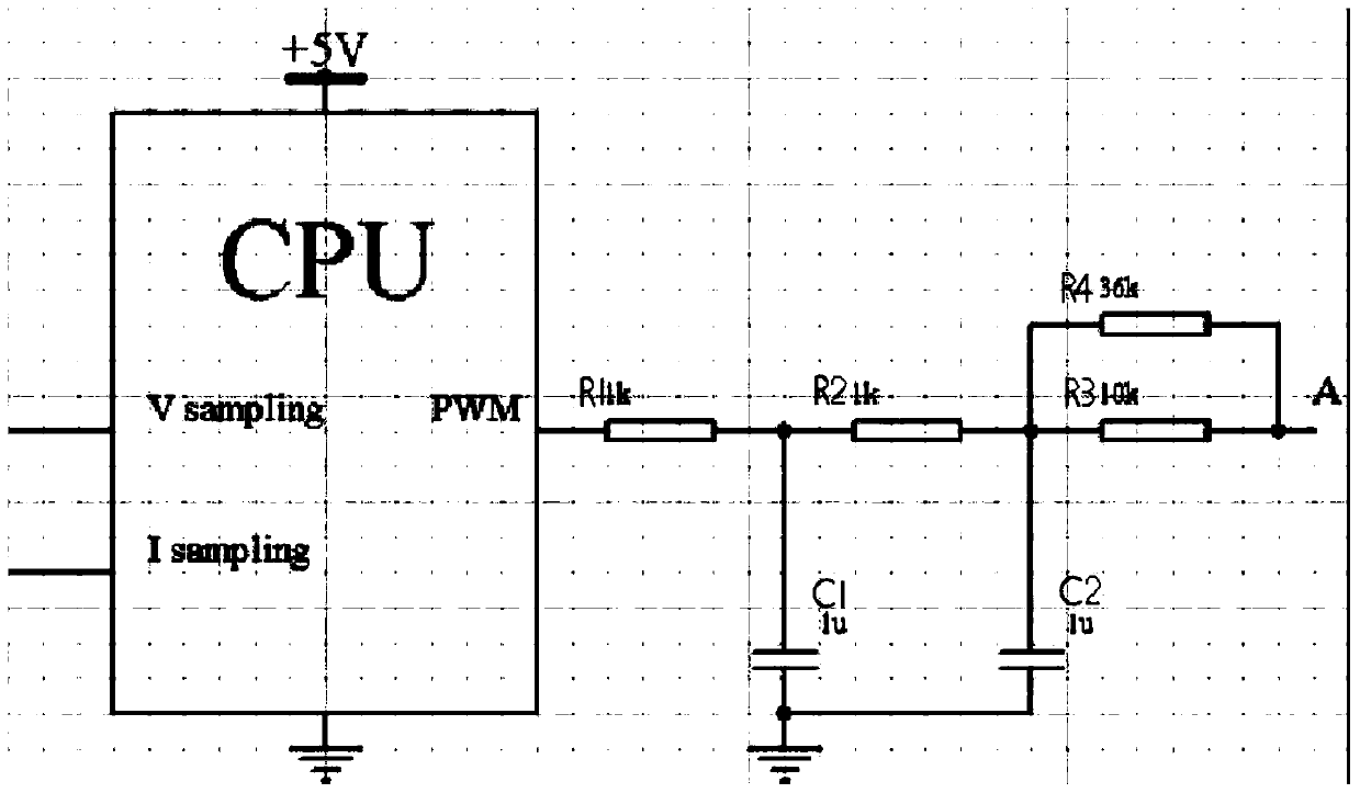
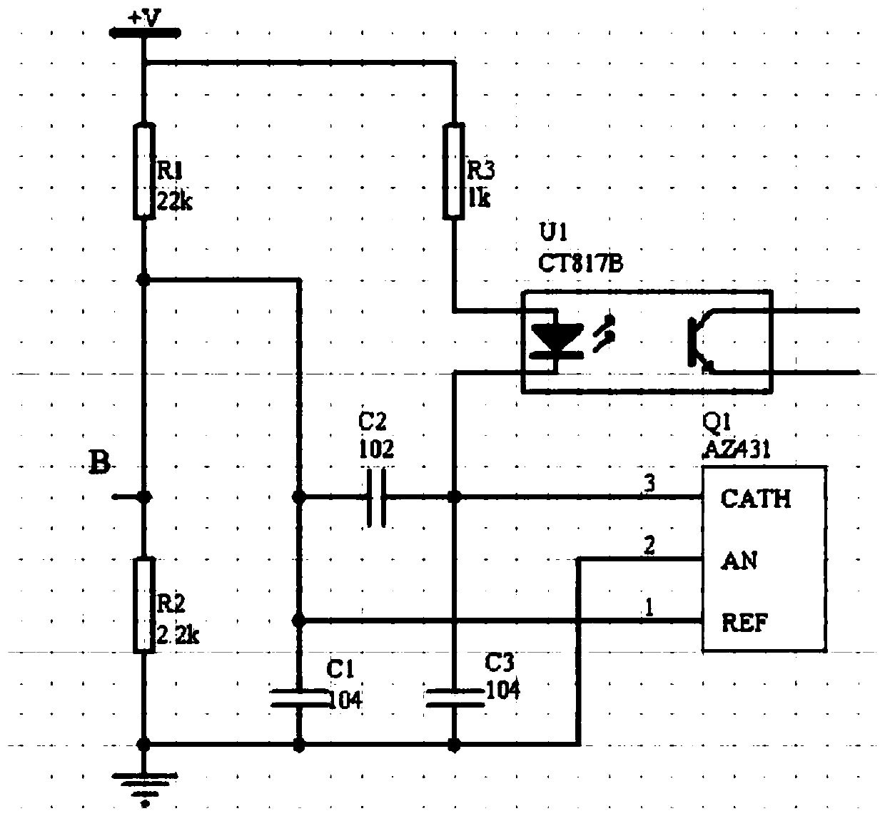
[0018] Such as Figure 1-2 As shown, a practical circuit that uses PWM to control the output voltage and current of the charger, including A point circuit and B point circuit,

[0019] A point circuit includes CPU, the first end of the CPU is the output end, the second end is set as the common ground end, and the third end is sequentially connected in series with resistor R1, resistor R2 and resistor R3, the active end of resistor R3 is point A, and the resistor R3 is connected in parallel with resistor R4, capacitor C1 is connected between resistor R1 and resistor R2, the movable end of capacitor C1 is set as a common ground terminal, one end of capacitor C2 is connected between resistor R2 and resistor R3, and the other end of capacitor C2 is connected to The active end of the capacitor C1 is connected;

[0020] The point B circuit includes a resistor R1, one end of the resistor R1 is the output end, the other end of the resistor R1 is connected in series with a resistor R2...


PUM


Abstract

The invention relates to the charger technology field and especially relates to a practical circuit for controlling an output voltage and a current of a charger through adopting a PWM mode. The circuit comprises an A-point circuit and a B-point circuit. The A point circuit comprises a CPU. A first end of the CPU is an output end. A second end is set as a common grounding end. A third end is successively connected with a resistor R1, a resistor R2 and a resistor R3 in series. A movable end of the resistor R3 is a point A. The resistor R3 is connected with a resistor R4 in parallel. A capacitorC1 is connected between the resistor R1 and the resistor R2. The movable end of the capacitor C1 is provided with a common grounding end. One end of a capacitor C2 is connected between the resistor R2and the resistor R3, the other end of the capacitor C2 is connected with the movable end of the capacitor C1, and the circuit can automatically adjust the output voltage and the output current of a finished high-power switch power supply so as to realize an automatic charging function of a high-power battery. The circuit is simple, a price is low and reliability is high.

Description

technical field [0001] The invention relates to the technical field of chargers, in particular to a practical circuit for controlling the output voltage and current of a charger by means of PWM. Background technique [0002] The core component of many high-power chargers on the market is a high-power switching power supply. There are many finished switching power supplies on the market, and their output voltage is adjustable within a certain range, which provides us with convenience for making chargers. For chargers, adjustable voltage means adjustable current, but this adjustable voltage and current must be automatically controlled, and the output voltage adjustment of the finished switching power supply is often realized through the adjustment of the analog potentiometer, which cannot be realized. Automatic control, which requires us to modify the circuit. Contents of the invention [0003] The object of the present invention is to provide a practical circuit for contro...

Claims


Application Information

Patent Timeline
Patent Type & Authority Applications(China)
IPC IPC(8): H02J7/00
CPCH02J7/007
Inventor 胡勤
Owner 合肥钦力电子有限公司
Why Eureka
Try Eureka