Assembling method based on multiple groups of optical lenses forming motor optical assembly

An optical lens and assembly method technology, applied in electrical components, color TV parts, TV system parts and other directions, can solve the problems of ignoring the assembly error of the optical lens and the carrier, vignetting and blurring, etc.

Active Publication Date: 2020-02-28
NINGBO SUNNY OPOTECH CO LTD
View PDF8 Cites 4 Cited by
  • Summary
  • Abstract
  • Description
  • Claims
  • Application Information

AI Technical Summary

Problems solved by technology

When the assembly error between the optical lens and the carrier is not considered, there will also be an angle α between the optical axis of the final optical element and the vertical axis
The included angle α will cause the farther away from the center of the optical axis, the greater the inclination during imaging, so in the area with a large inclination, it may cause bad imaging such as vignetting and blurring

Method used


Image

  • Assembling method based on multiple groups of optical lenses forming motor optical assembly
  • Assembling method based on multiple groups of optical lenses forming motor optical assembly
  • Assembling method based on multiple groups of optical lenses forming motor optical assembly

Examples


Embodiment approach

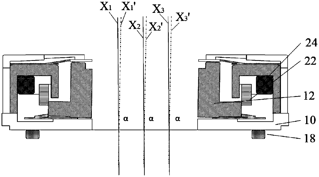
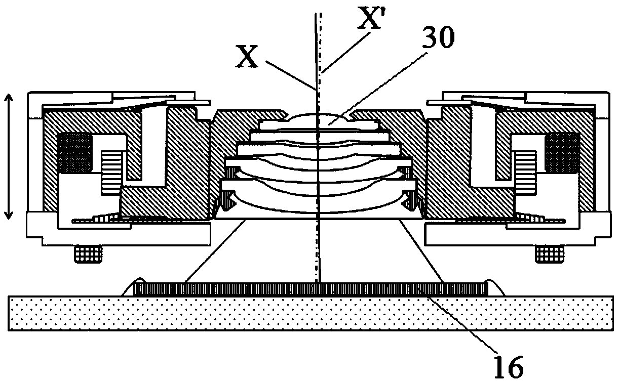
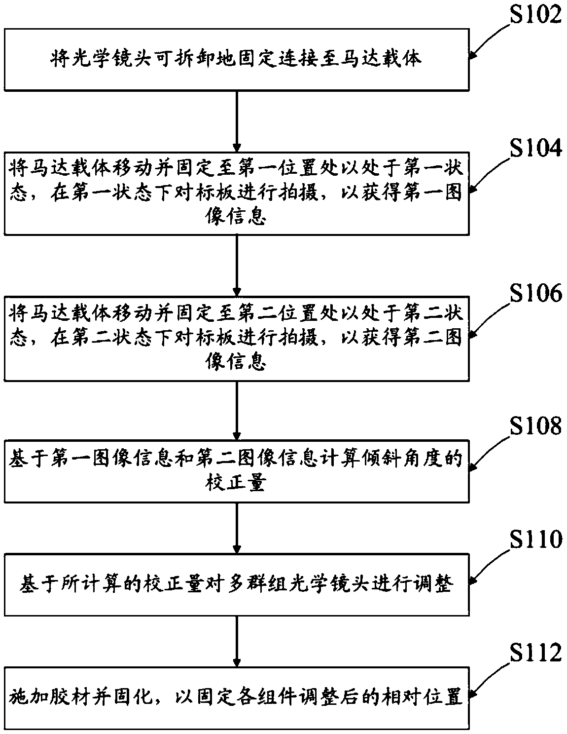
[0047] Such as image 3 As shown, in step S102 , the optical lens 30 is detachably fixedly connected to the motor carrier 12 . According to an exemplary embodiment of the present application, for example, the static tilt of the motor can be adjusted. In this case, there is no need to conduct a power test on the motor, only to test the rest position of the motor under different strokes. For example, it is possible to limit the position of the motor at different strokes (for example, use a jig for positioning). According to another exemplary embodiment, the distance from the target plate 16 to the camera test module can also be adjusted by using an existing height-adjustable bracket. For example, but not limited to, the method for testing a modular motor through MTF curves disclosed in Patent Application No. 201310063935.X.

[0048] After the optical lens 30 is installed in the motor carrier 12, in step S104, the motor carrier 12 can be moved and fixed to the first position, ...


PUM


Abstract

The invention discloses an assembling method based on multiple groups of optical lenses forming a motor optical assembly. The assembling method comprises the steps that the optical lenses are detachably and fixedly connected to a motor carrier; moving and fixing the motor carrier to a first position such that the carrier is in a first state; shooting the target plate in the first state to obtain first image information of the target plate; moving and fixing the motor carrier to a second position such that the carrier is in a second state; shooting the target plate in a second state to obtain second image information of the target plate; calculating a correction amount of the inclination angle based on the target plate first image information and the target plate second image information; and adjusting the multi-group optical lens based on the calculated correction amount.

Description

technical field [0001] The present application relates to the field of optical lens manufacturing, in particular to an assembly method based on multi-group optical lenses forming a motor optical assembly. The present application also relates to a camera module assembled by the method. Background technique [0002] In the process of manufacturing multi-group lenses into camera modules, in view of the large variety of camera modules, general camera modules are classified into AF modules and FF modules according to the presence or absence of focusing functions. In the AF module, in order to achieve high-efficiency production and assembly methods in the manufacturing industry, the camera module factory usually uses the lens provided by the lens factory and the motor provided by the motor factory. The camera module factory obtains the motor lens assembly by assembling the lens and the motor, and then installs the motor assembly on the circuit board to finally realize the install...

Claims


Application Information

Patent Timeline
Patent Type & Authority Applications(China)
IPC IPC(8): H04N5/225
CPCH04N23/55H04N23/00
Inventor 廖海龙钟凌陈振宇周广福叶超杨旭王雷
Owner NINGBO SUNNY OPOTECH CO LTD
Why Eureka
Try Eureka