Desanding device for shale gas exploitation

A shale gas and sand box technology, which is applied in the fields of fluid production, earthwork drilling, and liquid degassing, etc., can solve problems such as valve erosion, blockage of separator drainage pipelines, and complete removal of sand removers, thereby reducing Influence and burden reduction effect

Pending Publication Date: 2021-08-20
戴牛根
View PDF0 Cites 2 Cited by
  • Summary
  • Abstract
  • Description
  • Claims
  • Application Information

AI Technical Summary

Problems solved by technology

[0003] Shale gas mining generally adopts hydraulic fracturing, and the shale gas extracted from the well site generally includes three phases of gas, liquid and sand, and the solid impurities in it cannot be effectively and completely removed by the desander in the existing technology center , and then make the so

Method used


Image

  • Desanding device for shale gas exploitation
  • Desanding device for shale gas exploitation
  • Desanding device for shale gas exploitation

Examples


Embodiment Construction

[0024] The following will clearly and completely describe the technical solutions in the embodiments of the present invention with reference to the accompanying drawings in the embodiments of the present invention. Obviously, the described embodiments are only some, not all, embodiments of the present invention.

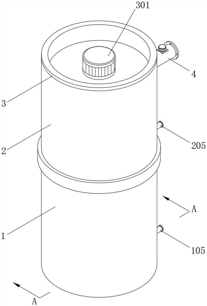
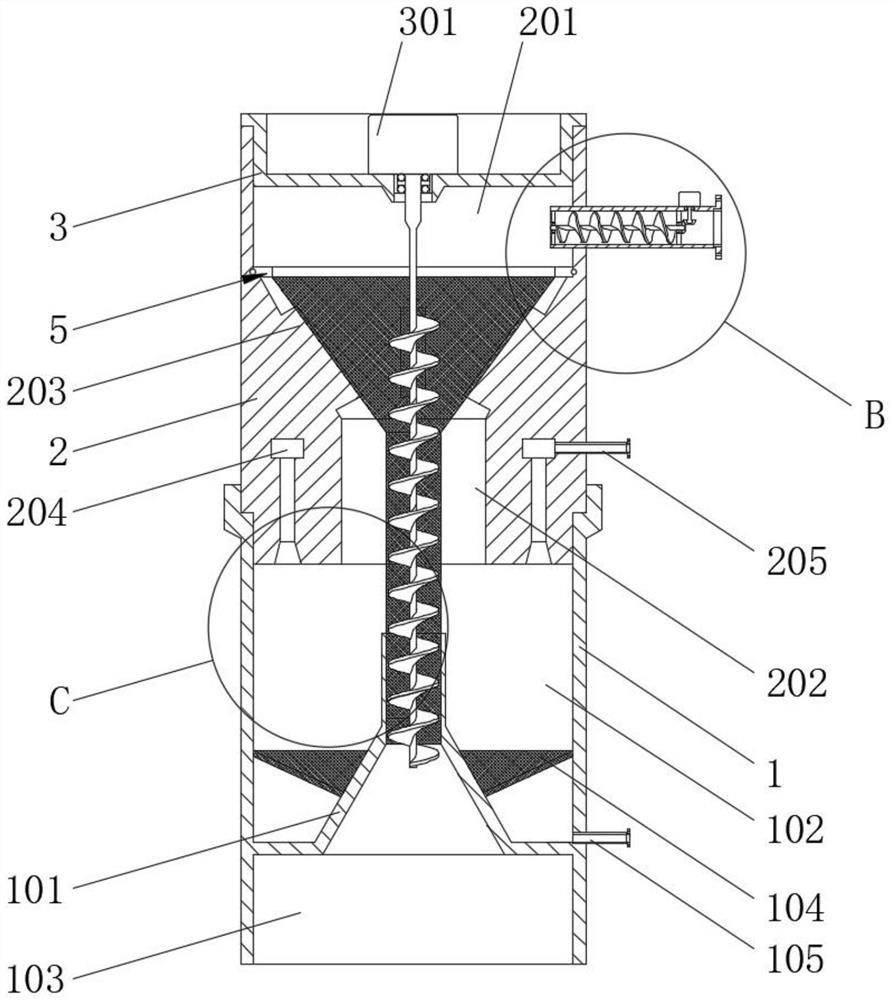
[0025] The present invention provides such Figure 1-6 The sand removal device shown for shale gas development includes a bearing box 1, a sand removal box 2, a motor carrier plate 3, a feed pipe 4 and a sand filter mechanism 5;

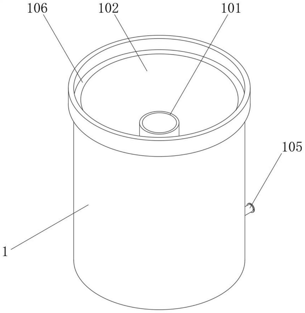
[0026] Both the carrying box 1 and the sand removal box 2 are cylindrical in shape, and the carrying box 1 and the sand removal box 2 are plugged and matched. The above carrying box 1 is constructed with a set of reversely docked conical buckets coaxial with the carrying box 1 101, the above-mentioned reverse docking conical bucket 101 divides the bearing box 1 into the upper drainage bin 102 and the lower sand discharge bin 103, the above-...


PUM


Abstract

The invention discloses a desanding device for shale gas exploitation. The desanding device comprises a bearing box, a desanding box, a motor carrier disc, a feeding pipe and a sand filtering mechanism; the bearing box and the desanding box are both constructed to be cylindrical; the bearing box and the desanding box are matched in an inserted connection mode; and a set of reverse butt joint conical hoppers coaxial with the bearing box are constructed in the bearing box; the bearing box is divided into an upper drainage bin and a lower sand discharging bin through the reverse butt joint conical hoppers; the desanding box is installed above the bearing box; a feeding bin is formed above the desanding box; a funnel-shaped separation bin is formed below the desanding box; and the funnel-shaped separation bin is communicated with the feeding bin and the drainage bin of the bearing box; the motor carrier disc is installed on the top of the desanding box and seals the feeding bin; a set of grooves for installation of a first driving motor is formed in the upper end of the motor carrier disc; and a set of auger feeding rods are arranged at the bottom end of the first driving motor. The desanding device for shale gas exploitation is reasonable in structure, easily achieves desanding work of fracturing fluid, reduces the workload of follow-up equipment and is recommended to be widely used.

Description

technical field [0001] The invention belongs to the technical field of mining equipment, and in particular relates to a sand removal device for shale gas development. Background technique [0002] Shale gas refers to organic matter-rich, mature dark mud shale or high-carbon mud shale, which has a certain commercial value due to the adsorption of organic matter or the existence of fractures and matrix pores in the rock, so that it is stored and preserved. , pyrolysis and natural gas of mixed origin. Shale gas is unconventional natural gas that occurs in reservoir rock series dominated by organic-rich shale. It is a continuously generated biochemical gas, thermogenic gas or a mixture of the two. It can exist in natural cracks and pores in a free state, exist in kerogen and clay particle surfaces in an adsorbed state, and store a very small amount in cheese in a dissolved state. In roots and asphaltene, the proportion of free gas is generally 20% to 85%. Shale gas drilling a...

Claims


Application Information

Patent Timeline
IPC IPC(8): B01D29/56B01D29/085B01D29/35B01D29/90B01D29/94B01D19/00E21B43/34
CPCB01D19/00B01D29/085B01D29/35B01D29/56B01D29/90B01D29/94E21B43/34
Inventor 戴牛根
Owner 戴牛根
Why Eureka
Try Eureka