Electromagnetic Brake Diagnosis Method, Device, and Electromechanical Brake System
A technology of electromagnetic brake and diagnosis method, applied in the direction of brake control system, brake safety system, brake, etc., can solve problems such as hidden dangers of driving behavior, and achieve the effect of reducing hidden dangers and improving reliability
- Summary
- Abstract
- Description
- Claims
- Application Information
AI Technical Summary
Problems solved by technology
Method used
Image

Examples
Embodiment 1
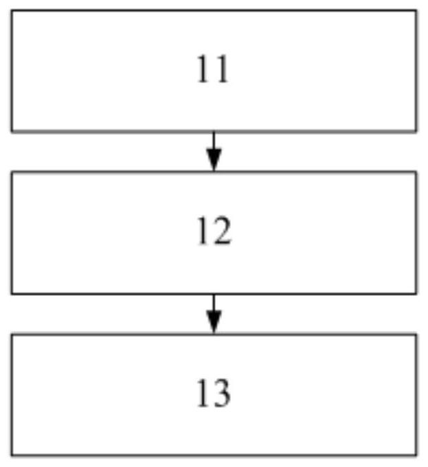
[0079] This embodiment provides a diagnostic method, such as figure 1 As shown, the diagnostic methods include:
[0080] 11. Control the conduction state of the high-voltage side switch and low-voltage side switch of the electromagnetic brake;
[0081] 12. When the switch is on and off respectively, obtain the voltage value of the high-voltage side of the electromagnetic brake and the voltage value of the low-voltage side of the electromagnetic brake;
[0082] 13. Determine whether there is a fault based on the level of the obtained voltage value.
[0083] The diagnostic method proposed in this embodiment is used to determine whether there is a fault in the circuit where the electromagnetic brake is located. The conduction of the high-voltage side switch and the low-voltage side switch is controlled based on the preset combination through the control chip, and the conduction of different switches can be obtained. Combination of voltage values.
[0084] Since the fault may c...
Embodiment 2
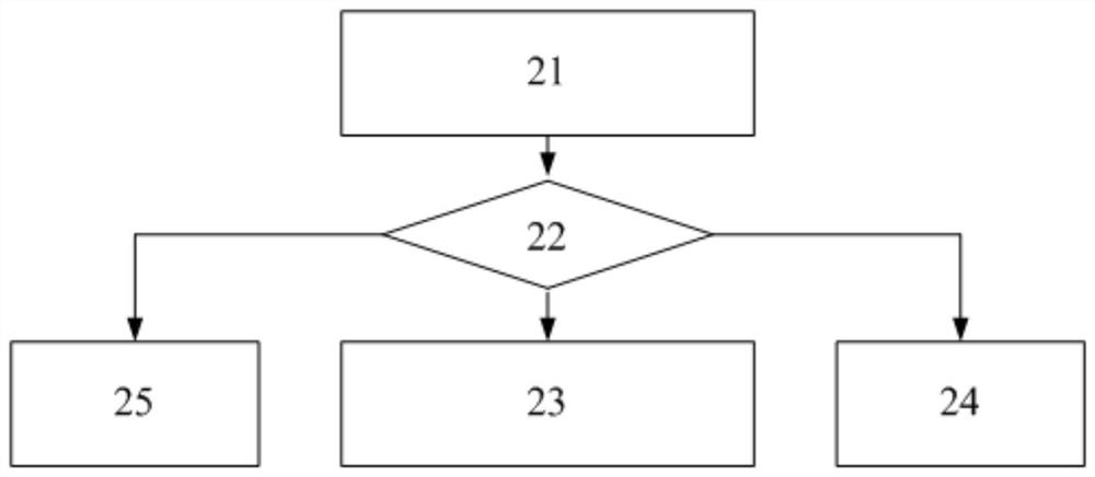
[0087] This embodiment provides a diagnostic method for diagnosing two possible faults in the working circuit of the electromagnetic brake.
[0088] (1) Determine whether there is a fault on the high-voltage side of the electromagnetic brake;
[0089] (2) Determine whether there is a fault on the low-voltage side of the electromagnetic brake.
[0090] In order to accurately determine the above two faults, two preset switch states are given in this embodiment, corresponding to the above two faults respectively.
[0091] Switching state 1 includes turning on the starting power of the electromagnetic brake, turning off the high-voltage side switch, and turning on the high-voltage side switch after a preset delay;
[0092] The second switching state includes turning on the starting power of the electromagnetic brake, turning on the high-voltage side switch, turning off the low-voltage side switch, and turning on the high-voltage side switch after a preset time delay.
[0093] Fo...
Embodiment 3
[0107] This embodiment provides a diagnostic method, which is different from the second embodiment in that it is used to determine whether there is a fault between the high-voltage side and the low-voltage side of the electromagnetic brake in the working circuit.
[0108] Before judging the above faults, it is also necessary to adjust the preset state of the switch, which corresponds to the switch state 2 in the second embodiment, and the specific content will not be repeated here.
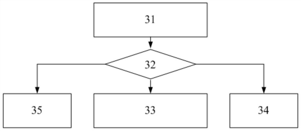
[0109] After the adjustment of the switch is completed, judge the obtained voltage value, such as Figure 4 shown, including:
[0110] 41. When the first voltage value is high level and the second voltage value is low level, obtain the current value flowing through the electromagnetic brake;
[0111] 42. If the current value is higher than the preset current upper limit threshold, it is determined that there is a short-circuit fault between the high-voltage side and the low-voltage side of the el...
PUM
 Abstract
Description
Claims
Application Information
 - R&D Engineer
- R&D Manager
- IP Professional
- Industry Leading Data Capabilities
- Powerful AI technology
- Patent DNA Extraction
Browse by: Latest US Patents, China's latest patents, Technical Efficacy Thesaurus, Application Domain, Technology Topic.
© 2024 PatSnap. All rights reserved.Legal|Privacy policy|Modern Slavery Act Transparency Statement|Sitemap