Reinforced telescopic device for corrugated pipe joints

The technology of a bellows section and a telescopic device is applied in the field of bellows, which can solve the problems of non-contraction at the joint, poor pressure resistance of the nozzle, poor connection strength, etc., and achieve the effects of high connection strength, good sealing effect and convenient operation.

Pending Publication Date: 2020-03-06
衡水瑟林科技有限公司
View PDF0 Cites 0 Cited by
  • Summary
  • Abstract
  • Description
  • Claims
  • Application Information

AI Technical Summary

Problems solved by technology

[0003] At present, the existing corrugated pipe connection devices have disadvantages such as poor connection strength, poor pressure resistance of the nozzle, poor sealing performance, and inflexibility of the connection. Therefore, how to design a connection structure to effectively overcome the above problems is a problem for those skilled in the art. an important research topic

Method used


Image

  • Reinforced telescopic device for corrugated pipe joints
  • Reinforced telescopic device for corrugated pipe joints
  • Reinforced telescopic device for corrugated pipe joints

Examples


Embodiment 1

[0034] The following is based on figure 1 , 3 -5 Describe in detail a reinforced bellows joint expansion device according to the embodiment of the present invention.

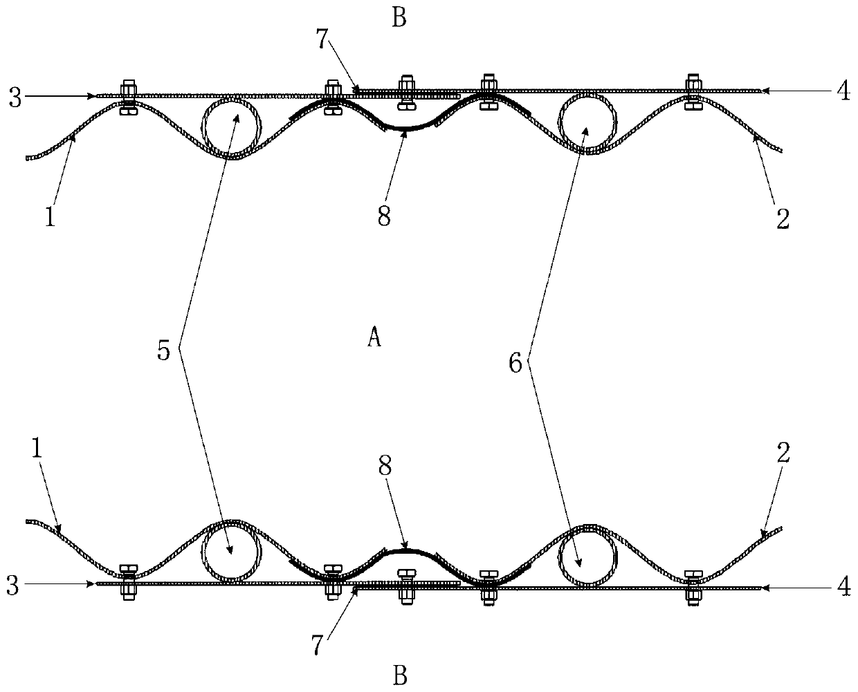
[0035] Such as figure 1 As shown, the embodiment of the present invention discloses a reinforced bellows joint expansion device, which is used to connect two adjacent bellows—the first bellows 1 and the second bellows 2 (wherein, in the figure, A is inside the pipe, B is the outside of the pipe), in order to prevent the damage of the pipe body caused by the uneven settlement of the foundation at the joint, the specific technical scheme is as follows:

[0036] The reinforced bellows joint telescopic device includes a first telescopic sheet 3 fixed on the outer surface of the first bellows 1 and a second telescopic sheet 4 fixed on the outer surface of the second bellows 2, the first telescopic sheet 3 and the second Two telescopic sheets 4 are curved steel plates.

[0037] Such as Figure 3-5 As shown, the f...

Embodiment 2

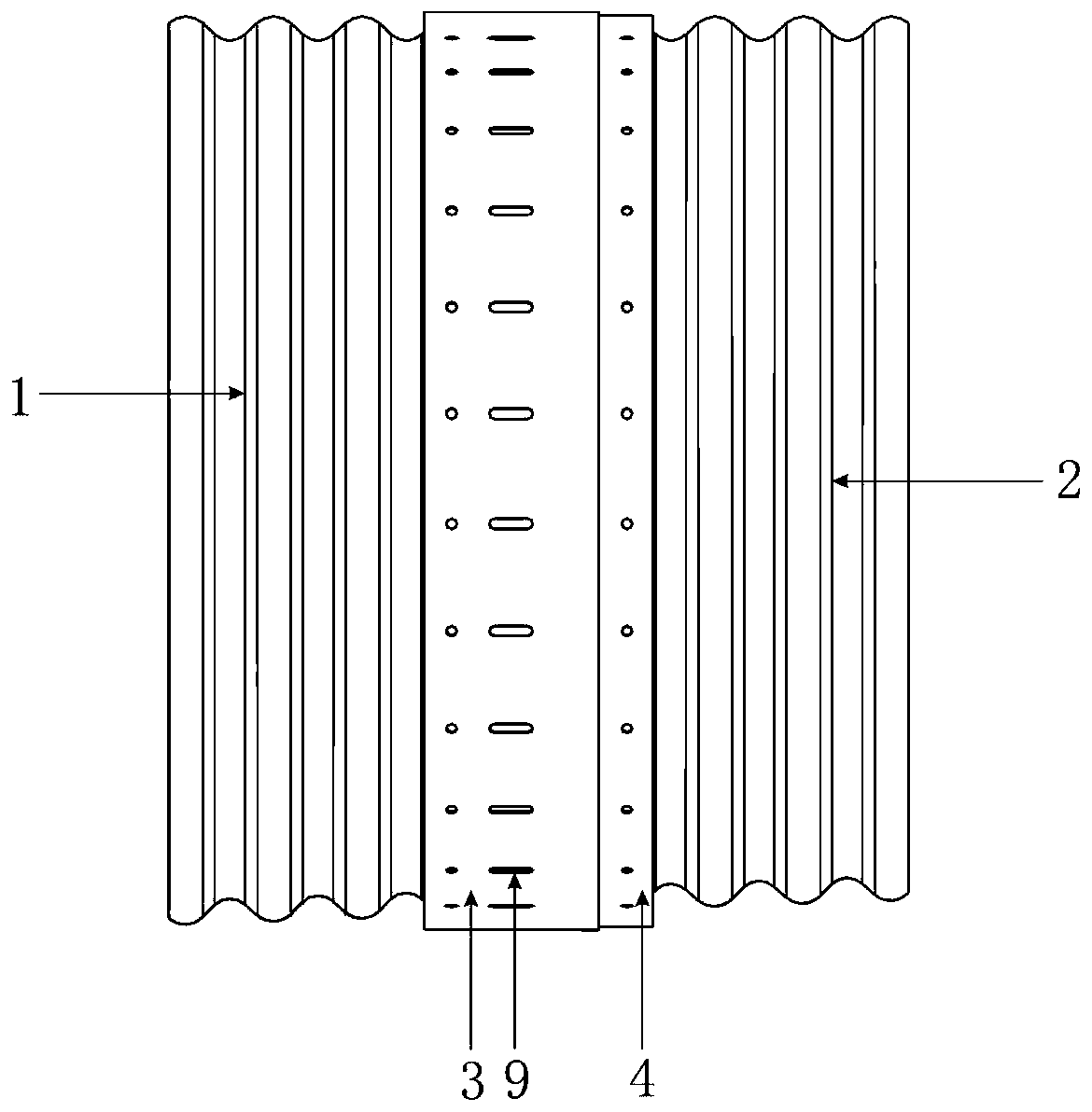
[0044] Such as Figure 2-4 , 6, the structure of the first telescopic sheet 3 and the second telescopic sheet 4 in the reinforced bellows joint telescopic device of this embodiment is basically the same as the structure of the telescopic sheet in Embodiment 1, the only difference is that the first telescopic There is only one row of circular holes on the sheet 3 and the second telescopic sheet 4, and the corrugated pipe is also provided with corresponding circular holes, and the bolts pass through a row of circular holes 10 to firmly connect the telescopic sheet and the corrugated pipe.

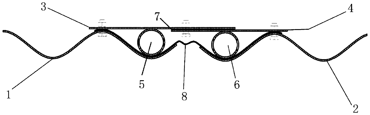
[0045] Such as figure 2 As shown, the above embodiment 2 is suitable for the working condition where the edge of the corrugated pipe section is a trough.

[0046] When installing a reinforced bellows joint telescopic device of the present invention, first put the second sealing plate 8 and the two reinforcing rings on the corresponding positions of the two bellows, and then put the first se...


PUM


Abstract

The invention discloses a reinforced telescopic device for corrugated pipe joints. The reinforced telescopic device is used for connecting a first corrugated pipe with a second corrugated pipe which are adjacent to each other, and comprises a first telescopic sheet and a second telescopic sheet; the first telescopic sheet is fixed to the outer surface of the first corrugated pipe; the second telescopic sheet is fixed to the outer surface of the second corrugated pipe; the first telescopic sheet is connected with the second telescopic sheet through two slotted holes and correspondingly matchedbolts; a first reinforcing ring is arranged between the first telescopic sheet and the first corrugated pipe; a second reinforcing ring is arranged between the two telescopic sheet and the second corrugated pipe; a first sealing plate is arranged in the middle of the connection part between the first telescopic sheet and the second telescopic sheet; and second sealing plates are integrally arranged in the middle of the connection part between the first telescopic sheet and the first corrugated pipe and the middle of the connection part between the second telescopic sheet and the second corrugated pipe. The reinforced telescopic device has the advantages of simple structure, high convenience in operation, good sealing effect, high connection strength, high pressure resistance of a pipe orifice and telescopic connection part, and can be widely used for connecting corrugated pipes in the fields of machines, engineering application and the like.

Description

technical field [0001] The invention relates to the technical field of bellows, in particular to a reinforced bellows joint expansion device. Background technique [0002] The bellows is a cylindrical thin-wall corrugated shell with multiple transverse corrugations. The bellows mainly include metal bellows, corrugated expansion joints, corrugated heat exchange tubes, diaphragm diaphragm boxes and metal hoses. Metal bellows mainly play the role of compensating pipeline thermal deformation, shock absorption, and absorbing pipeline settlement deformation. Multiple metal bellows need to be connected, and the strength and sealing of the connection have become issues that technicians need to focus on. [0003] At present, the existing corrugated pipe connection devices have disadvantages such as poor connection strength, poor pressure resistance of the nozzle, poor sealing performance, and non-stretchable joints. Therefore, how to design a connection structure to effectively over...

Claims


Application Information

Patent Timeline
Patent Type & Authority Applications(China)
IPC IPC(8): F16J3/04
CPCF16J3/048
Inventor 郭琳
Owner 衡水瑟林科技有限公司
Why Eureka
Try Eureka