Multi-path optical module

An optical module and optical chip technology, applied in the directions of light guides, optics, optical components, etc., can solve the problems of difficult coupling and alignment of multi-channel optical modules, achieve simple and efficient assembly process, ensure coupling success rate, and meet time requirements. The effect of progress requirements

Pending Publication Date: 2020-03-06
NO 34 RES INST OF CHINA ELECTRONICS TECH GRP
View PDF0 Cites 1 Cited by
  • Summary
  • Abstract
  • Description
  • Claims
  • Application Information

AI Technical Summary

Problems solved by technology

[0006] The present invention aims to solve the problem that the existing multi-channel optical module is difficult to achieve coupling alignment, and provides a multi-channel optical module

Method used


Image

  • Multi-path optical module
  • Multi-path optical module
  • Multi-path optical module

Examples


Embodiment Construction

[0022] In order to make the object, technical solution and advantages of the present invention clearer, the present invention will be further described in detail below in conjunction with specific examples. It should be noted that the directional terms mentioned in the examples, such as "upper", "lower", "middle", "left", "right", "front", "rear", etc., are only referring to the directions of the drawings. Therefore, the directions used are only for illustration and are not intended to limit the protection scope of the present invention.

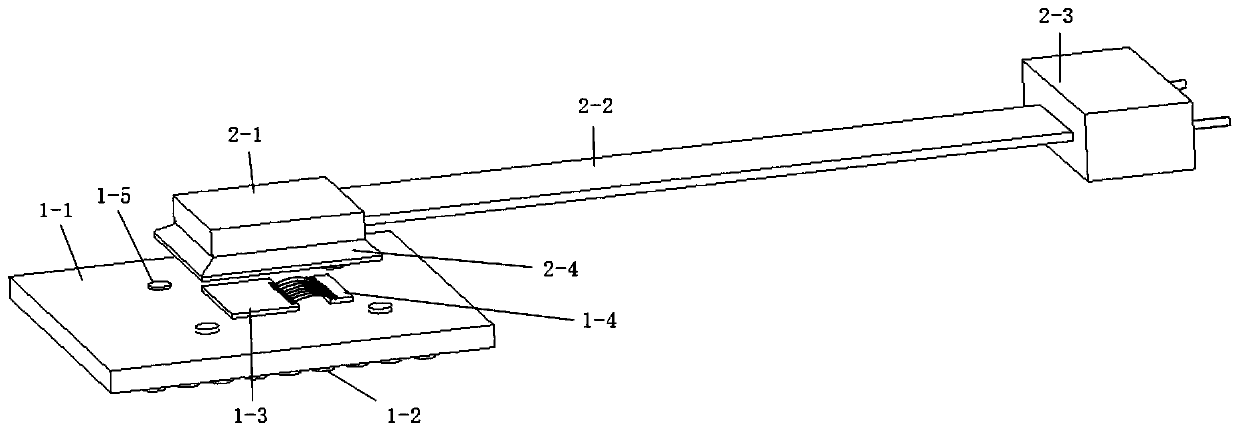
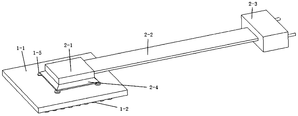
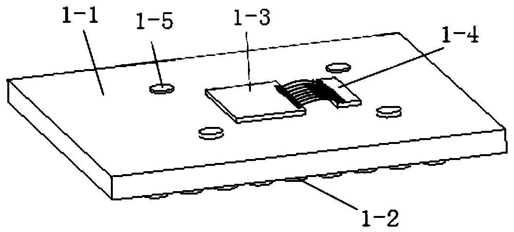
[0023] see Figure 1-4 , a multi-channel optical module is composed of a core circuit unit 1 and an optical fiber array coupling unit 2. The core circuit unit 1 is mainly composed of a printed circuit board 1-1, a BGA pad array 1-2, an electrical chip array 1-3 and an optical chip array 1-4. The BGA pad array 1-2 is soldered on the lower surface of the printed circuit board 1-1. The electric chip array 1-3 and the optical chip array 1-4 a...


PUM


Abstract

The invention discloses a multipath optical module, and the module is composed of a core circuit unit and an optical fiber array coupling unit. A positioning support cover is additionally arranged atthe lower edge of a lens assembly; the positioning supporting cover is in an inverted and through horn shape, the necking end of the positioning supporting cover is fixedly connected with the lower edge of the lens assembly, and the flaring end of the positioning supporting cover faces downwards. More than three positioning points are arranged on the printed circuit board around an electric chip array and an optical chip array; the number of the positioning points is the same as that of the vertex angles of the flared end of the positioning supporting cover, the positions of the positioning points are opposite, and when the lens assembly drives the positioning supporting cover to cover the electric chip array and the optical chip array, all the vertex angles of the flared end of the positioning supporting cover are right opposite to and overlapped with all the positioning points. According to the invention, the assembling efficiency can be improved, so the requirement of batch production can be met; and meanwhile, the core circuit unit can be protected.

Description

technical field [0001] The invention relates to the technical field of optical fiber communication, in particular to a multi-channel optical module. Background technique [0002] With the promotion and in-depth application of large-capacity and high-speed optical communications, the demand for optical modules is increasing day by day, and the market demand is also constantly developing in the direction of multi-channel, miniaturization, and high reliability. The market demand for optical modules also puts forward new requirements for the optical coupling process involved in the packaging of multi-channel optical modules. [0003] The existing multi-channel optical module consists of two parts: a core circuit unit and an optical fiber array coupling unit. In the production process, since the core circuit unit and the fiber array coupling unit are two relatively independent components, it is necessary to cover the lens assembly of the fiber array coupling unit on the optical ...

Claims


Application Information

Patent Timeline
Patent Type & Authority Applications(China)
IPC IPC(8): G02B6/42
CPCG02B6/424G02B6/4244G02B6/4245
Inventor 唐绍宇伍颖汤科
Owner NO 34 RES INST OF CHINA ELECTRONICS TECH GRP
Why Eureka
Try Eureka