
Installation and adjustment device and method of optical fiber collimator of multi-path optical fiber rotary connector

A fiber collimator and rotary connector technology, which is applied in the directions of instruments, optics, light guides, etc., can solve the problems of position offset, difficulty in adjusting the fiber collimator, and small size of the fiber collimator.

Active Publication Date: 2021-09-10
CHINA ELECTRONICS TECH GRP CORP NO 14 RES INST
View PDF4 Cites 4 Cited by
  • Summary
  • Abstract
  • Description
  • Claims
  • Application Information

AI Technical Summary

Problems solved by technology

[0003] In addition, due to the angle between the optical axis of the parallel light emitted by the fiber collimator and the mechanical axis, there is an interference problem between the fiber collimators of the multi-channel fiber optic rotary connector; the size of the fiber collimator is small, and the transmission mechanism Easy to produce position shift when fixed
These have brought difficulties to the adjustment of the fiber collimator of the multi-channel fiber optic rotary connector

Method used


Image

  • Installation and adjustment device and method of optical fiber collimator of multi-path optical fiber rotary connector
  • Installation and adjustment device and method of optical fiber collimator of multi-path optical fiber rotary connector
  • Installation and adjustment device and method of optical fiber collimator of multi-path optical fiber rotary connector

Examples


Embodiment 1

[0026] The installation and adjustment of the multi-channel optical fiber rotary connector fiber collimator includes two steps:

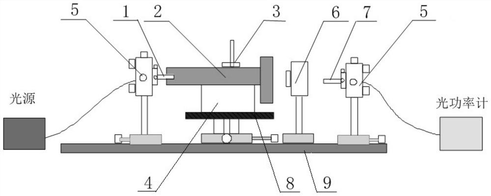
[0027] Install and adjust the input fiber collimator, find out the ideal position of the output end installation hole of the transmission mechanism of the multi-channel optical fiber rotary connector, and then set the output end installation hole of the transmission mechanism of the multi-channel optical fiber rotary connector at this ideal position , can realize the coupling alignment of the fiber collimator, and avoid the interference problem between the fiber collimators of the multi-channel fiber rotary connector;

[0028] Install the output fiber collimator in the output mounting hole of the multi-channel fiber rotary connector transmission mechanism, and adjust the output fiber collimator, so that the fiber alignment of the multi-channel fiber rotary connector can be finally solved. To solve the coupling installation problem of the fiber colli...


PUM


Abstract

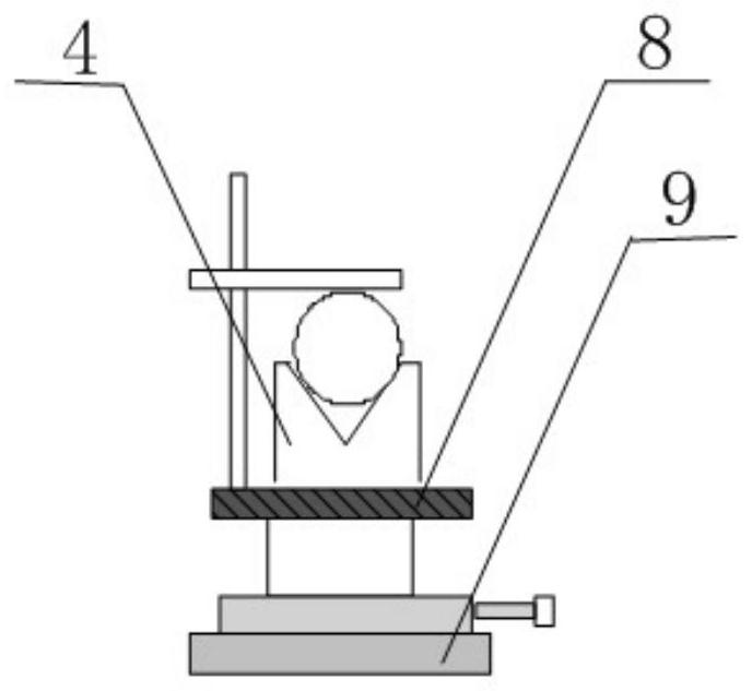
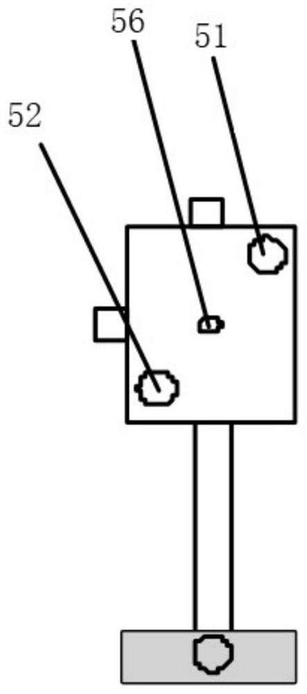
The invention discloses an installation and adjustment device and method of an optical fiber collimator of a multi-path optical fiber rotary connector and belongs to the technical field of optical signal rotary transmission. The installation and adjustment method comprises the following steps: fixing an input end optical fiber collimator on a five-dimensional adjustment frame, connecting an input end with a light source, and installing an output end into a transmission mechanism mounting hole; adjusting the five-dimensional adjustment frame to enable the light spot position of the output end to be located at the ideal light spot position; performing coupling coarse tuning according to the index on an optical power meter until the insertion loss index of the optical fiber collimator meets the coupling coarse tuning requirement; adjusting the five-dimensional adjustment frame, and making the output end optical fiber collimator screwed into the transmission mechanism mounting hole; and rotating the input end of the transmission mechanism, and adjusting the five-dimensional adjustment frame according to the index change of the optical power meter until the indexes on the optical power meter all meet the installation and adjustment requirements. According to the invention, the coupling installation problem of the optical fiber collimators of the multi-path optical fiber rotary connector can be solved, and the coupling installation and adjustment precision of the optical fiber collimators is improved.

Description

technical field [0001] The invention belongs to the technical field of optical signal rotation transmission, and in particular relates to a device and method for installing and adjusting an optical fiber collimator of a multi-channel optical fiber rotary connector. Background technique [0002] The optical fiber rotary connector can realize the 360°rotation transmission of the optical signal from the fixed part to the rotating part. The multi-channel optical fiber rotary connector adopts the optical transmission principle of the Dove prism. Coupling after the beam, but the coupling alignment of the fiber collimator is very difficult, the slight position and angle deviation will lead to a rapid drop in the insertion loss of the technical index, and the insertion loss in the rotation process must be balanced, so how to realize the alignment of the fiber collimator and The installation and positioning of the transmission mechanism of the optical fiber rotary connector is the ke...

Claims


Application Information

Patent Timeline
Patent Type & Authority Applications(China)
IPC IPC(8): G02B6/36
CPCG02B6/3604G02B6/366
Inventor 徐明胡长明魏忠良
Owner CHINA ELECTRONICS TECH GRP CORP NO 14 RES INST
Learn More