Magnetic disk device and control method thereof
A disk device and control circuit technology, applied in the direction of memory address/allocation/relocation, instrumentation, generation of response errors, etc.
- Summary
- Abstract
- Description
- Claims
- Application Information
AI Technical Summary
Problems solved by technology
Method used
Image

Examples
no. 1 Embodiment approach
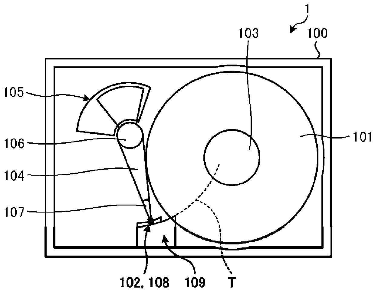
[0021] figure 1 It is a diagram showing an example of the hardware configuration of the magnetic disk drive according to the first embodiment. exist figure 1 2 shows the configuration inside the casing 100 when the upper cover of the magnetic disk device 1 is removed. like figure 1 As shown, the magnetic disk device 1 includes a magnetic disk 101, a magnetic head 102 for reading and writing data, and the like.
[0022] The magnetic disk 101 is a disk medium capable of reading and writing data. The magnetic disk 101 is provided with one of the two magnetic disks (the first magnetic disk 101), and the other (the second magnetic disk 101 (refer to Figure 7 )) is disposed on the back side of the first magnetic disk 101 ( figure 1 the depth side of the paper). In addition, in the present embodiment, the number of magnetic disks is described as two, but the number of magnetic disks may be only one, or may be three or more.
[0023] The first magnetic disk 101 and the second ...
no. 2 Embodiment approach
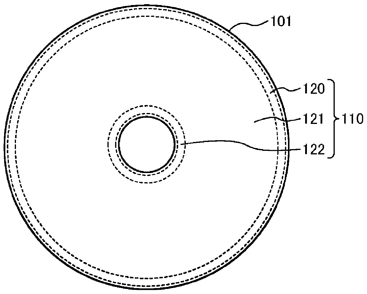
[0112] In the first embodiment, when there is no empty area in the replacement area 122 ( Figure 10 No in S301), the control circuit 20 maintains the operation mode as the normal mode and executes adding an area to the replacement area 122 .
[0113] In the second embodiment, an example will be described in which the operation mode is temporarily changed from the normal mode to the write-inhibit mode before adding an area to the spare area 122 .
[0114] In addition, in the second embodiment, only the processing different from that in the first embodiment will be described. Description of the same processing as in the first embodiment is omitted.
[0115] Figure 11 It is a flowchart showing an example of the procedure related to the update of the allocation of each area (media cache area 120 , user area 121 , and replacement area 122 ) in the second embodiment.
[0116] The control circuit 20 (for example, the MPU 25 ) determines whether there is an empty area, that is, a...
no. 3 Embodiment approach
[0129] In the second embodiment, the size of the area to be added to the replacement area 122 is set in advance.
[0130] In the third embodiment, an example in which the size of the area to be added to the replacement area 122 can be set by the host computer 2 will be described.
[0131] In addition, in the third embodiment, only the processes different from those in the first and second embodiments will be described. Description of the same processing as in the first and second embodiments is omitted.
[0132] Figure 12 It is a flowchart showing an example of the procedure related to the updating of the allocation of each area (the medium cache area 120 , the user area 121 , and the replacement area 122 ) in the third embodiment.
[0133] In S501 and S502, perform the Figure 11 The same processing as in S401 and S402.
[0134] In the third embodiment, the extension command can include designation of a size. The size may also be specified by a ratio relative to the siz...
PUM
 Abstract
Description
Claims
Application Information
 - R&D Engineer
- R&D Manager
- IP Professional
- Industry Leading Data Capabilities
- Powerful AI technology
- Patent DNA Extraction
Browse by: Latest US Patents, China's latest patents, Technical Efficacy Thesaurus, Application Domain, Technology Topic.
© 2024 PatSnap. All rights reserved.Legal|Privacy policy|Modern Slavery Act Transparency Statement|Sitemap