Multi-sample continuous testing device for viscosity of solid propellant slurry
A technology of solid propellant and test device, applied in the direction of measuring device, flow characteristics, instrument, etc., can solve the problems of inability to plug and insert at will, low efficiency of slurry viscosity test, inability to meet the simultaneous testing of multiple samples, etc., and achieve high test efficiency. , Simple structure, novel design effect
Inactive Publication Date: 2020-03-13
SHANGHAI AEROSPACE CHEM ENG INST
View PDF14 Cites 1 Cited by
- Summary
- Abstract
- Description
- Claims
- Application Information
AI Technical Summary
Problems solved by technology
During the test period, the rotor can only be placed in the slurry to keep warm, and cannot be removed and inserted at will. As a result, one rotational visco
Method used
View moreImage
Smart ImageViewing Examples

Examples
 PUM
 Abstract
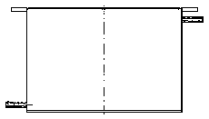
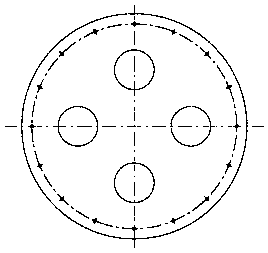
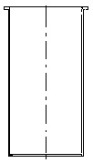
The invention provides a multi-sample continuous testing device for viscosity of solid propellant slurry. The multi-sample continuous testing device is composed of a constant-temperature circulating water tank, a sample cup, a sample heat preservation barrel, a rotary viscometer, a rotor and a rotary disc. The sample heat preservation barrel is externally connected with the constant-temperature circulating water tank and circulating water is introduced into the sample heat preservation barrel; the sample cup is arranged in the sample heat preservation barrel; the sample heat preservation barrel is arranged on the rotary disc; the sample heat preservation barrel and the constant-temperature circulating water tank are used for preserving heat of the sample cup containing a sample; a cavity is formed in the sample heat preservation barrel; circulating water is introduced into the sample heat preservation barrel; the sample heat preservation barrel is externally connected with the constant-temperature circulating water tank; and a circulating water inlet is formed in the lower end of the outer wall of the sample heat preservation barrel. Compared with the prior art, the device has theadvantages of being novel in design, simple in structure, easy to operate, adjustable in temperature, convenient to clean, small in test data error, high in test efficiency and the like.
Description
technical field [0001] The invention relates to the technical field of performance testing of composite solid propellants, in particular to a multi-sample continuous test device for the viscosity of solid propellant slurry. Background technique [0002] Composite solid propellant is the main component of solid motor, and its production is a relatively complicated process, which has gone through processes such as weighing, premixing, mixing, mandrel disposal, pouring, curing, demoulding and shaping. Among them, mixing, pouring and solidification are the process of reacting the liquid slurry mixed with various materials into a solid composite solid propellant. [0003] The rheological properties of the composite solid propellant slurry directly affect the mixing and pouring process of the composite solid propellant, and the process performance. For the composite solid propellant using the pouring molding process, the slurry must have the rheological properties to smoothly flo...
Claims
Login to view more Application Information
Patent Timeline
 IPC IPC(8): G01N11/14
CPCG01N11/14
Inventor 黄丽萍李辉万代红程连潮陆振超李京修洪杨
Owner SHANGHAI AEROSPACE CHEM ENG INST
- R&D Engineer
- R&D Manager
- IP Professional
Why Eureka
- Industry Leading Data Capabilities
- Powerful AI technology
- Patent DNA Extraction
Try Eureka
Browse by: Latest US Patents, China's latest patents, Technical Efficacy Thesaurus, Application Domain, Technology Topic.
© 2024 PatSnap. All rights reserved.Legal|Privacy policy|Modern Slavery Act Transparency Statement|Sitemap