
Circular stirrup machining device

A processing device and technology for stirrups, applied in the field of circular stirrup processing devices

Pending Publication Date: 2020-03-17
中国人民解放军63926部队
View PDF0 Cites 2 Cited by
  • Summary
  • Abstract
  • Description
  • Claims
  • Application Information

AI Technical Summary

Problems solved by technology

[0004] The invention proposes a round stirrup processing device to solve the technical problem of how to process round stirrups with different diameters

Method used


Image

  • Circular stirrup machining device
  • Circular stirrup machining device

Examples


Embodiment Construction

[0012] In order to make the purpose, content and advantages of the present invention clearer, the specific implementation manners of the present invention will be further described in detail below in conjunction with the accompanying drawings and embodiments.

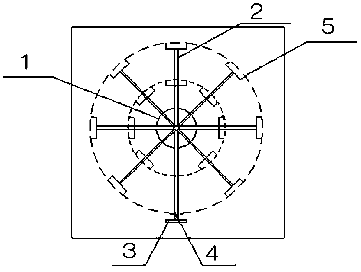
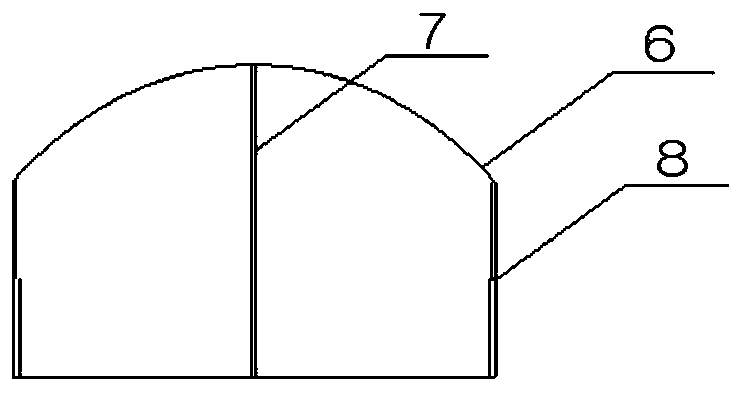
[0013] This embodiment proposes a circular stirrup processing device, its structure is as follows figure 1 As shown, it includes a central disk 1, a telescopic strut 2, a steel bar fixing part 3 and an arc member 5. Wherein, the lower part of the central disc 1 is connected with the motor, and can be driven to rotate by the motor. A plurality of telescopic poles 2 are connected around the central disk 1, and the end of one telescopic pole 2 is connected with a steel bar fixing part 3, and the steel bar fixing part 3 is provided with a steel bar fixing port 4 for processing One end of the steel bar of the round stirrup is fixed. The ends of other telescopic poles 2 are connected with arc-shaped members 5, which are use...


PUM


Abstract

The invention provides a circular stirrup machining device. The circular stirrup machining device comprises a center disk, telescopic support rods, a steel bar fixing part and a plurality of arc-shaped components. According to the circular stirrup machining device, the plurality of movable arc-shaped components are mounted on the center disk, and telescopic side rods are arranged on the two sidesof the interiors of the arc-shaped components. The circular stirrup machining device can machine different diameters and curvatures of circular stirrups and has the good adaptability to meet differentmachining requirements.

Description

technical field [0001] The invention belongs to the technical field of steel bar processing in building construction, and in particular relates to a circular stirrup processing device. Background technique [0002] At present, the force-bearing members of buildings are often designed as cylindrical concrete columns, and circular stirrups need to be used in the manufacture of cylindrical concrete columns. The circular stirrup processing devices in the prior art can only be processed to form single-diameter Round stirrups have greater limitations and lower processing efficiency. Contents of the invention [0003] (1) Technical problems to be solved [0004] The invention provides a round stirrup processing device to solve the technical problem of how to process round stirrups with different diameters. [0005] (2) Technical solution [0006] In order to solve the above-mentioned technical problems, the present invention proposes a circular stirrup processing device, which...

Claims


Application Information

Patent Timeline
Patent Type & Authority Applications(China)
IPC IPC(8): B21F1/00
CPCB21F1/00
Inventor 张孝春李云涛张润武王群王敏舟朱乔磊石旭单绿芝张兴军吴靓
Owner 中国人民解放军63926部队
Learn More